
What Causes Clutch Disc Failure in Heavy-Duty Trucks?
Understanding Why Heavy-Duty Truck Clutch Components Fail Prematurely
In the demanding world of commercial transportation, the friction coupling system between engine and transmission endures extraordinary stress. A clutch disc in a heavy-duty truck can experience engagement forces exceeding 1,500 lb-ft of torque during routine operations. When this critical component fails, fleet operators face costly downtime, expensive repairs, and potential safety hazards on the road.
Understanding the root causes of premature friction plate failure is essential for fleet managers, owner-operators, and maintenance technicians. This comprehensive guide examines every major factor that leads to coupling component degradation in Class 7 and Class 8 trucks. We also provide actionable troubleshooting strategies and prevention methods backed by decades of heavy-duty powertrain expertise.
Whether you manage a fleet of fifty trucks or maintain a single rig, recognizing early warning signs can save thousands in repair costs. According to a commercial vehicle maintenance survey published in early 2026, unplanned drivetrain repairs account for approximately 23% of total fleet maintenance expenditure, with friction component failures representing the single largest category.
How the Engagement System Works in Heavy-Duty Applications
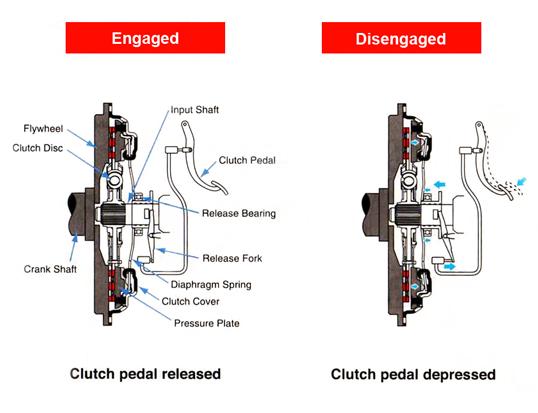
Before diagnosing failure modes, it is important to understand how the power transfer system operates under commercial loads. The engagement mechanism in a heavy-duty truck functions as a wear component designed to smoothly connect the engine's rotating mass to the transmission input shaft while absorbing shock loads during gear changes.
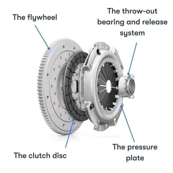
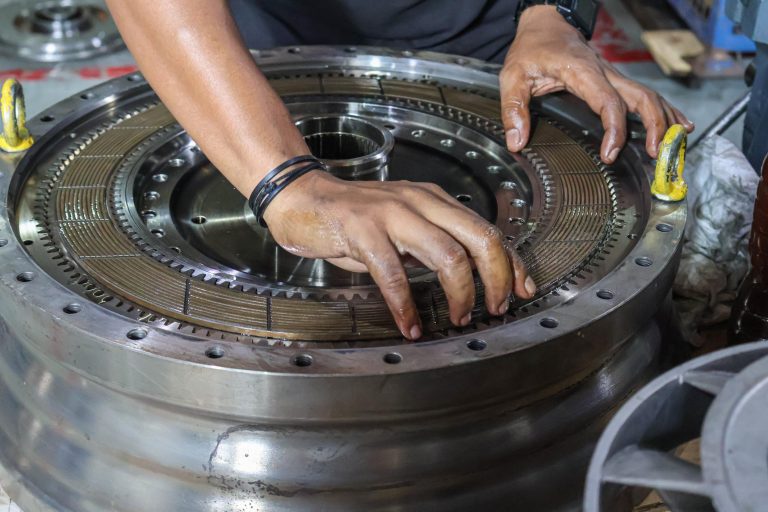
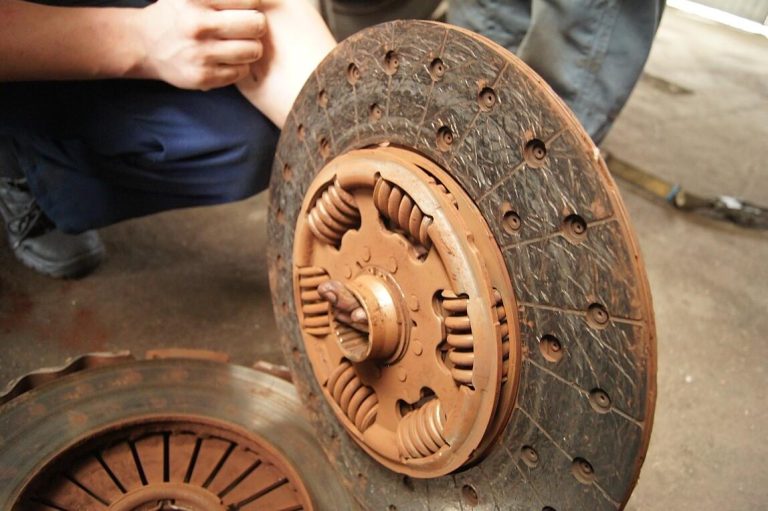
The system consists of several interrelated parts working in concert. The driven plate sits between the engine flywheel and the clamping mechanism, featuring high-temperature friction material bonded to both sides of a steel carrier plate. Internal torsion damper springs within the hub absorb rotational vibration, protecting downstream drivetrain components from destructive harmonics.
When the driver releases the engagement pedal, the clamping mechanism forces the driven plate against the flywheel face. This creates a friction bond that transmits engine torque through the splined hub into the gearbox input shaft. The entire engagement process must happen smoothly within fractions of a second while handling torque loads that would destroy passenger vehicle components.
In heavy-duty applications, this assembly faces uniquely harsh conditions. Stop-and-go delivery routes, mountain grade descents requiring frequent downshifting, and heavy trailer loads all compound wear beyond what standard duty cycles would predict. Understanding these operational realities is the first step toward preventing premature component degradation.
Key Differences Between Light-Duty and Heavy-Duty Systems
Heavy-duty engagement systems differ fundamentally from their light-vehicle counterparts. Commercial truck components must handle sustained torque loads five to eight times greater than passenger cars. The driven plate diameter in a Class 8 tractor typically measures 15.5 inches compared to 9-10 inches in passenger vehicles.
Material composition also differs significantly. Commercial friction linings use ceramic-metallic compounds or woven materials designed for extreme heat resistance. These materials sacrifice some engagement smoothness in exchange for dramatically improved thermal stability and longevity under load.
Additionally, heavy-duty systems employ dual-plate or even triple-plate configurations for the highest torque applications. Each additional driven surface increases torque capacity without requiring a proportionally larger housing diameter, which is constrained by bell housing geometry.
1. Overheating Due to Excessive Slipping
Thermal damage represents the single most common failure mode in heavy-duty engagement systems. When the driven plate slips excessively against the flywheel face, kinetic energy converts directly into heat. Temperatures can spike above 400°C within seconds during aggressive engagement under load, far exceeding the thermal tolerance of most friction compounds.
Excessive slipping typically originates from driver behavior, mechanical maladjustment, or a combination of both factors. New or inexperienced drivers may "ride" the engagement pedal, maintaining partial disengagement while the vehicle is under power. This generates tremendous heat concentrated in the friction lining surface.
Hill starts with heavy loads present another common thermal challenge. A fully loaded combination vehicle weighing 80,000 pounds requires precise modulation to launch on an incline. Prolonged slipping during these maneuvers can destroy friction linings in a remarkably short time if repeated frequently throughout a shift.
The thermal damage cascade follows a predictable pattern. Initial overheating causes the organic binders in friction compounds to break down, releasing gases that create a boundary layer between contact surfaces. This gaseous layer actually reduces friction coefficients, causing even more slipping and heat generation in a destructive feedback loop.

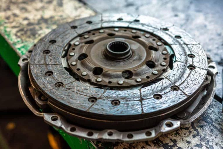
Signs of Thermal Damage
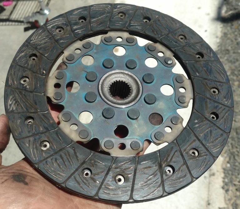
Identifying heat-related degradation early can prevent catastrophic failure. Visual inspection reveals characteristic blue-black discoloration on the flywheel and clamping mechanism faces. The friction lining surface may appear glazed or glassy, indicating that material has melted and resolidified.
Operationally, drivers notice a burnt smell—often described as similar to burning paper or overheated brakes. Engagement becomes inconsistent, with the pedal "grab point" migrating toward the top of pedal travel. In advanced cases, the vehicle may struggle to maintain speed on grades even with the pedal fully released.
| Temperature Range | Effect on Friction Lining | Reversibility |
|---|---|---|
| Below 200°C | Normal operating range, no degradation | N/A |
| 200°C – 300°C | Accelerated wear, binder softening begins | Partially reversible |
| 300°C – 400°C | Glazing, reduced friction coefficient | Requires resurfacing or replacement |
| Above 400°C | Material decomposition, cracking, delamination | Irreversible—replacement required |
Troubleshooting Thermal Issues
When overheating is suspected, begin by measuring the remaining lining thickness on the driven plate. Use a micrometer to check multiple points across the friction surface. The clutch disc thickness minimum specification varies by manufacturer but typically falls between 7.5mm and 8.0mm for 15.5-inch heavy-duty plates when measured at the rivets.
Inspect the flywheel surface for heat checking—a pattern of fine cracks that indicates repeated thermal cycling. Light heat checking can sometimes be addressed through machining, but deep cracks require flywheel replacement to prevent premature wear of the new friction component.
Evaluate the release mechanism for proper free play. Insufficient free play means the release bearing maintains slight contact with the diaphragm spring fingers, preventing full clamping force from reaching the driven plate. This partial engagement creates the exact slipping condition that generates excessive heat.
Review vehicle operating data if electronic logging devices are available. Look for patterns of extended engagement times during hill starts or frequent low-speed maneuvering that might indicate driver training opportunities or route optimization needs.
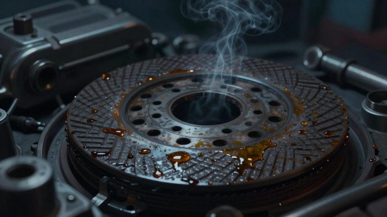
2. Contamination with Oil or Grease
Fluid contamination ranks as the second most destructive failure mode for heavy-duty friction components. Even small quantities of oil or grease on friction surfaces dramatically reduce the coefficient of friction, causing slipping, shuddering, and accelerated material degradation. The porous nature of many friction compounds means that contamination penetrates below the surface, making cleaning or light machining ineffective.
Common contamination sources include leaking rear main engine seals, transmission front bearing retainer seals, or over-lubrication of the release bearing and pilot bearing. In heavy-duty applications, the larger component dimensions and higher operating temperatures can accelerate seal degradation, particularly in engines with high mileage.
Grease contamination from the splined hub represents another frequent issue. During installation, technicians may apply excessive lubricant to the input shaft splines. Centrifugal force then migrates this grease outward onto the friction surfaces during operation. Only a thin film—approximately 0.1mm—of petroleum-based contamination is sufficient to cause noticeable engagement problems.
Coolant leaks from failing freeze plugs or transmission cooler lines can also contaminate the bell housing environment. Glycol-based coolants are particularly destructive to friction materials because they create a persistent slippery film that resists evaporation at normal operating temperatures.
Identifying Contamination Sources
Diagnosis begins with removing the bell housing inspection cover (where equipped) and visually examining the friction surfaces. Oil contamination typically appears as dark, wet-looking areas on the lining face. Grease contamination may show a more localized pattern, often originating from the hub area and spreading outward in a centrifugal pattern.
Check the rear main seal area for active leaking. With the engine running, observe whether oil accumulates at the bottom of the bell housing. A small amount of seepage is normal on high-mileage engines, but active dripping indicates a seal that requires replacement before any friction component service will be effective.
Transmission input shaft seal integrity should also be verified. Remove the inspection cover and look for gear oil residue on internal components. Transmission fluid contamination often has a distinctive sulfur odor and amber or dark brown coloration that differs from engine oil.
Contamination Prevention Strategies
Preventing fluid contamination requires attention during both maintenance procedures and ongoing seal monitoring. During installation, apply only the manufacturer-specified amount of lubricant to input shaft splines—typically a very thin film using a brush, not a grease gun. Excess lubricant should be wiped away completely before assembly.
Implement a seal inspection protocol during routine maintenance intervals. Rear main seals and transmission front seals should be inspected at every oil change by checking the bell housing drain hole for active leakage. Early intervention on minor seepage prevents the catastrophic contamination that destroys expensive drivetrain components.
Consider using synthetic-compatible seal conditioners in engine oil for older vehicles where minor rear main seal seepage is detected. These additives can restore elastomer flexibility in aging seals, potentially extending service life without requiring disassembly for seal replacement.
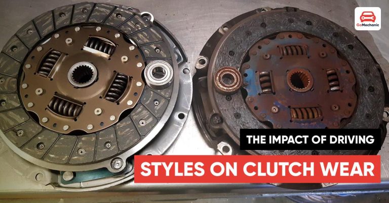
3. Excessive Load and Aggressive Driving
Commercial vehicles frequently operate at or near their gross vehicle weight rating, placing enormous demands on the engagement system. However, consistent overloading beyond rated capacity accelerates wear exponentially rather than linearly. A vehicle regularly operated at 10% over GVWR may experience friction component life reduction of 30-40% compared to properly loaded vehicles.
Aggressive driving habits compound load-related stress significantly. Rapid engagement techniques—commonly called "dumping" the pedal—create momentary torque spikes that exceed steady-state ratings. These impact loads stress not only the friction material but also the hub assembly, damper springs, and splined connections that transmit power downstream.
In vocational applications like construction, logging, or waste management, vehicles routinely encounter conditions that demand repeated low-speed engagement under maximum load. These duty cycles far exceed what highway applications demand, and component selection must reflect this reality. A friction assembly rated for over-the-road service may last only a fraction of its rated life in severe-duty vocational applications.
Understanding the relationship between load, engagement speed, and component life helps fleet operators make better decisions about component selection and driver training investments. The energy that the friction assembly must absorb during each engagement cycle increases with both vehicle mass and the speed differential between engine and transmission at the moment of engagement.
Energy Absorption During Engagement
The physics of engagement help explain why excessive loads are so destructive. The energy absorbed by friction surfaces during each engagement event follows this relationship: Energy = ½ × I × (ω₁ - ω₂)², where I represents the system moment of inertia and ω values represent engine and transmission speeds at engagement.
Heavier loads increase the effective moment of inertia the system must accelerate, requiring longer slip times to achieve synchronization. This extended slip period generates proportionally more heat and wear. A 20% increase in vehicle weight can result in 40-50% more energy absorption per engagement cycle due to the squared relationship.
| Vehicle Loading | Relative Energy per Engagement | Expected Component Life Impact |
|---|---|---|
| Empty (bobtail) | 1.0x (baseline) | Maximum rated life |
| 50% GVWR | 1.8x | ~75% of rated life |
| Full GVWR | 3.2x | ~55% of rated life |
| 10% Over GVWR | 4.1x | ~35% of rated life |
| 20% Over GVWR | 5.3x | ~25% of rated life |
Driver Training as a Cost-Saving Strategy
Investing in proper driver training delivers measurable returns in reduced drivetrain maintenance costs. Fleet data from a 2025 North American logistics study showed that targeted engagement technique training reduced friction component failures by 34% across a 200-vehicle fleet within 12 months of implementation.
Key training points include matching engine RPM to road speed before engagement, using progressive rather than abrupt pedal release techniques, and recognizing situations where the vehicle should be repositioned rather than attempting to launch under excessive load or on steep grades.
Modern telematics systems can monitor engagement behavior in real-time, flagging events where excessive slipping or harsh engagement occurs. This data enables targeted coaching conversations with specific drivers rather than generic training sessions that may not address individual habits.
4. Improper Clutch Adjustment
Correct mechanical adjustment is fundamental to engagement system longevity in heavy-duty applications. Unlike modern passenger vehicles with self-adjusting hydraulic systems, many commercial trucks still utilize mechanical or pneumatic-assisted linkages that require periodic manual adjustment as the friction material wears.
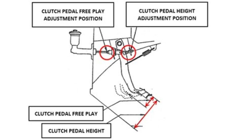
Insufficient free play—the distance the pedal travels before the release mechanism contacts the diaphragm spring fingers—is perhaps the most common maladjustment. Without adequate free play, the release bearing maintains constant contact with the clamping mechanism. This prevents full clamping force from being applied to the driven plate, creating a condition of perpetual partial slipping.
Excessive free play creates different but equally problematic symptoms. When too much pedal travel is consumed before disengagement begins, the driver may not achieve full separation between the driven plate and flywheel. This causes gear grinding during shifts, premature synchronizer wear, and potential damage to the splined hub from forced engagement against a partially coupled drivetrain.
Self-adjusting mechanisms, while reducing manual maintenance requirements, can also fail. Worn adjustment components may ratchet past their intended range, or contamination can prevent the automatic adjustment mechanism from operating properly. These systems still require periodic verification even though they reduce routine adjustment frequency.
Proper Adjustment Procedures
Always refer to the specific manufacturer specifications for the engagement system installed. General guidelines for most heavy-duty mechanical linkage systems include maintaining 12-15mm of free play at the release fork, which translates to approximately 25-38mm of free pedal travel measured at the pedal pad.
For hydraulic systems, verify that the master cylinder pushrod has proper clearance to the piston—typically 0.5-1.0mm. Without this clearance, fluid cannot fully return to the reservoir during pedal release, causing hydraulic pressure to remain in the system and prevent full engagement force application.
After any adjustment, verify proper operation through a series of functional tests. With the engine running and vehicle stationary, fully depress the pedal and wait five seconds before selecting reverse gear. Grinding or resistance indicates incomplete disengagement that requires further adjustment.
Self-Adjusting Mechanism Verification
Trucks equipped with self-adjusting systems require different inspection approaches. Locate the adjustment mechanism—typically mounted on the release fork or within the bell housing—and verify that it moves freely through its designed range. Contamination with road grime or corrosion can immobilize these components, effectively disabling the self-adjusting feature.
Check that the wear indicator (where equipped) shows within the normal range. Many manufacturers incorporate a visual indicator that shows remaining adjustment travel. When this indicator reaches its limit, the friction assembly has reached the end of its serviceable life regardless of remaining lining thickness.
Document adjustment readings during each preventive maintenance interval. Trending this data over time reveals wear rates that can predict when replacement will be needed, allowing planned maintenance rather than emergency roadside repairs that cost significantly more in both parts and downtime.
5. Worn or Damaged Pressure Plate
The pressure plate is the clamping mechanism that applies force to hold the driven friction assembly against the flywheel face. When this component wears or becomes damaged, it directly impacts the ability to maintain proper engagement, regardless of the friction lining condition. Understanding how the clamping mechanism fails helps technicians diagnose root causes rather than simply replacing the driven plate and encountering repeat failure.
Diaphragm spring fatigue represents the most common clamping mechanism failure mode. Over millions of engagement cycles, the spring steel fingers lose their heat-treated temper and deliver progressively less clamping force. This manifests as slipping under load—initially only during high-torque situations like launching on grades, but eventually during normal highway operation.
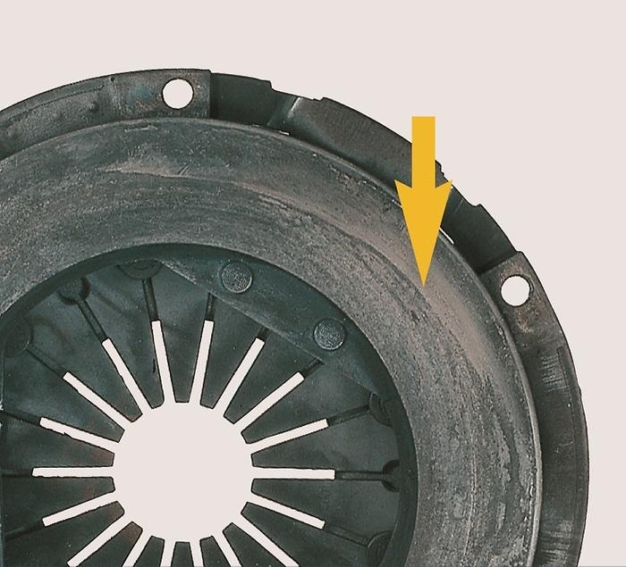
Thermal distortion of the pressure ring (the flat surface that contacts the driven plate) creates engagement inconsistency. When heat causes warping, only portions of the friction surface make full contact. This concentrates wear in localized areas, creating uneven lining wear patterns that produce vibration and chatter during engagement.
Wear on the diaphragm finger contact surfaces where the release bearing makes contact can also cause problems. Grooved or worn fingers change the mechanical advantage relationship, altering pedal feel and potentially preventing full engagement force even when the pedal is fully released. To understand the operational differences between these two components, researching the clutch disc vs pressure plate difference provides valuable diagnostic insight.
Inspection Criteria for the Clamping Mechanism
During any friction assembly replacement, the clamping mechanism must be thoroughly inspected and typically replaced as part of a complete kit. Reusing a worn clamping mechanism with a new driven plate is a false economy that frequently results in premature failure of the new component within a fraction of its expected service life.
Measure the pressure ring surface for flatness using a precision straightedge and feeler gauges. Maximum allowable warpage for most heavy-duty applications is 0.15mm (0.006 inches). Any measurement exceeding this specification requires replacement—machining the pressure ring is not recommended as it alters the spring geometry and clamping force characteristics.
Inspect the diaphragm spring fingers for uniform height. Place the assembly on a flat surface and measure finger tip height at multiple points around the circumference. Variation exceeding 0.5mm indicates thermal distortion or fatigue that will prevent even release bearing contact and cause dragging or incomplete disengagement.
Examine the drive strap connections (the thin metal straps that connect the pressure ring to the cover assembly). Cracked or fatigued drive straps allow the pressure ring to shift laterally during operation, creating vibration and inconsistent clamping force distribution across the friction surface.
When to Replace vs. When to Inspect Only
| Condition Found | Action Required | Consequence of Ignoring |
|---|---|---|
| Finger wear grooves < 0.5mm deep | Monitor at next interval | Gradual pedal feel change |
| Finger wear grooves > 0.5mm deep | Replace clamping mechanism | Incomplete engagement, slipping |
| Pressure ring warpage < 0.10mm | Acceptable for reuse with new driven plate | Minimal impact if within spec |
| Pressure ring warpage > 0.15mm | Replace entire assembly | Hot spots, uneven wear, chatter |
| Heat discoloration (blue/purple) | Replace—spring temper compromised | Progressive loss of clamping force |
| Cracked drive straps | Immediate replacement | Catastrophic failure risk |
6. Poor Quality or Improperly Installed Friction Components
Component quality varies enormously in the aftermarket parts landscape. Budget-grade friction assemblies may use inferior lining compounds, substandard damper springs, or imprecise manufacturing tolerances that result in dramatically shortened service life. For fleet operators focused on total cost of ownership rather than initial purchase price, selecting reputable product category brand suppliers with documented quality standards delivers superior long-term value.
Friction material quality directly determines thermal resilience, wear rate, and engagement characteristics. Premium ceramic-metallic compounds designed for heavy-duty applications maintain stable friction coefficients across a wide temperature range. Inferior materials may perform adequately when cool but fade dramatically under thermal stress, initiating the destructive slipping-overheating cycle discussed earlier.
Hub and damper spring quality affects drivetrain vibration levels and component longevity beyond the friction assembly itself. Poorly calibrated damper springs allow torsional vibrations to reach the transmission, accelerating gear and bearing wear. Weak springs may collapse entirely under heavy torque loads, causing metallic rattling noises and potential hub failure.
Manufacturing dimensional accuracy matters because the driven plate must run true between the flywheel face and clamping mechanism with minimal axial runout. Plates with excessive runout (wobble) create cyclic loading variations that cause engagement shudder and accelerate wear on the clamping mechanism contact surfaces.
Installation Errors That Cause Premature Failure
Even quality components fail rapidly when installed incorrectly. Improper alignment during installation tops the list of technician-induced failures. Without a proper alignment tool (or with a worn tool that does not accurately center the driven plate), the transmission input shaft must force the plate into alignment during reassembly. This can bend the hub or damage splines before the truck even returns to service.
Contamination during installation represents another common error. Touching friction surfaces with bare hands deposits skin oils that create localized hot spots during initial break-in. Failing to clean the flywheel surface of rust preventative coatings, old friction dust, or machining residue similarly compromises initial engagement performance.
Incorrect torque on flywheel bolts or bell housing bolts can create alignment issues that manifest only under load. Uneven flywheel bolt torque causes flywheel face runout, while improper bell housing bolt torque can distort the housing enough to create input shaft misalignment. Both conditions accelerate driven plate wear and cause engagement inconsistency.
Forgetting to lubricate the pilot bearing, or using incorrect lubricant on the input shaft splines, creates conditions for future failure. A dry pilot bearing generates friction and heat in the crankshaft bore, while incorrect spline lubricant may not withstand the temperatures present in the bell housing environment.
Quality Verification Checklist
Before installing any friction assembly, perform these verification steps to confirm component quality and readiness for service:
- Verify part number matches the vehicle application exactly—similar-looking components from different applications may have different spline counts, lining diameters, or damper spring rates
- Check driven plate axial runout by placing on a known-true mandrel and rotating while measuring with a dial indicator (maximum 0.5mm TIR for most applications)
- Verify friction lining thickness at multiple points—new linings should measure within 0.2mm of specification uniformly
- Confirm damper spring free play by rotating the hub relative to the lining carrier—movement should be smooth with no binding or excessive free play
- Inspect spline engagement by test-fitting on the transmission input shaft—the plate should slide freely without forcing but without excessive radial play
- Verify clamping mechanism finger height uniformity and release bearing contact surface condition
7. Lack of Regular Maintenance
Preventive maintenance is the foundation of reliable engagement system operation. Unlike engine oil changes or brake inspections, which have clear visible indicators and scheduled intervals, the friction coupling assembly often operates within a sealed bell housing where problems develop invisibly until they reach a critical stage.
Regular inspection of the bell housing environment should be incorporated into every preventive maintenance schedule. At minimum, technicians should check the inspection cover opening (where equipped) for evidence of contamination, excessive friction dust accumulation, or unusual odors at every scheduled service—typically aligned with oil change intervals.
Linkage or hydraulic system maintenance directly impacts friction assembly life. Mechanical linkage pivot points require periodic lubrication to maintain smooth operation. Cable-operated systems need adjustment as cables stretch with use. Hydraulic systems require fluid level checks and periodic fluid replacement to prevent seal degradation from moisture-contaminated fluid.
The release bearing—a sealed unit in most heavy-duty applications—has a finite service life that should be tracked alongside the friction assembly. Many technicians replace the release bearing only when the driven plate is replaced, but bearing failure between friction component services can cause catastrophic damage to the clamping mechanism fingers, turning a bearing replacement into a complete assembly replacement.
Recommended Maintenance Intervals
| Maintenance Action | Highway Application | Vocational/Severe Duty |
|---|---|---|
| Visual bell housing inspection | Every oil change (25,000 mi) | Every oil change (10,000 mi) |
| Linkage adjustment verification | Every 50,000 miles | Every 25,000 miles |
| Hydraulic fluid level check | Monthly | Weekly |
| Hydraulic fluid replacement | Every 2 years or 200,000 miles | Annually or 100,000 miles |
| Release bearing replacement | With every friction assembly change | With every friction assembly change |
| Flywheel inspection/resurface | With every friction assembly change | With every friction assembly change |
| Complete assembly replacement | 500,000–750,000 miles typical | 150,000–300,000 miles typical |
Documentation and Trending
Trending free play reduction between adjustments reveals the friction material wear rate for each specific vehicle and application. Once established, this trend allows maintenance planners to schedule replacements during planned maintenance windows rather than reacting to failures. A vehicle consuming free play at 1.5mm per 25,000 miles, starting from 15mm total adjustment range, can be predicted to need service within approximately 250,000 miles.
Fleet management systems can automate this trending and generate alerts when vehicles approach their predicted service threshold. This data-driven approach—supported by comprehensive technical support resources—transforms maintenance from reactive to proactive, reducing emergency repair costs and improving vehicle availability.
How to Prevent Friction Assembly Failure
Prevention is always more cost-effective than repair in heavy-duty commercial applications. A comprehensive prevention strategy addresses all seven failure modes simultaneously through a combination of proper component selection, correct installation practices, appropriate driver training, and systematic maintenance protocols.
Component Selection Strategy
Selecting the right friction assembly begins with honestly assessing the vehicle's actual duty cycle. Highway tractors pulling consistent loads across flat terrain have dramatically different requirements than refuse trucks performing hundreds of engagement cycles per shift in stop-and-go operation. The best clutch disc for high performance cars philosophy applies equally to commercial vehicles—match the component to the actual demand, not just the vehicle weight rating.
Consider ceramic-metallic friction materials for vocational applications where thermal loading is severe. While these materials require slightly more pedal effort and produce a firmer engagement feel, their thermal stability under repeated heavy-load engagement cycles provides dramatically improved longevity in severe-duty applications.
For mixed-duty fleets where vehicles may serve multiple roles, organic friction materials with enhanced thermal resistance offer a balanced compromise between engagement smoothness and heat tolerance. These premium compounds cost more initially but their extended service life typically delivers lower total cost per mile.
Consult application guides from the component manufacturer or visit our product category system to identify the correct assembly specification for your specific chassis, engine, and transmission combination. Using the wrong application—even if it physically fits—can result in premature failure due to mismatched torque capacity or thermal ratings.
Installation Best Practices
Professional installation practices eliminate a significant percentage of premature failures attributed to quality issues. Follow these essential procedures during every engagement assembly replacement:
- Clean the flywheel surface with a non-petroleum solvent (brake cleaner) to remove all residue before inspecting for damage or wear
- Measure flywheel surface runout with a dial indicator—maximum 0.13mm (0.005") for most applications; resurface or replace if exceeded
- Use a proper alignment tool sized for the specific pilot bearing bore and input shaft spline to center the driven plate precisely
- Apply lubricant sparingly to input shaft splines using a brush, then wipe away excess; over-lubrication is the most common installation contamination source
- Torque all fasteners to manufacturer specification in the proper sequence—star pattern for flywheel bolts, sequence specified for bell housing
- Verify release bearing travel and linkage adjustment before returning the vehicle to service
- Perform a break-in procedure: 15-20 easy engagements allowing cooling time between each, avoiding full-load operation for the first 500 miles
Driver Training Fundamentals
Effective driver training focuses on three core principles that maximize engagement component longevity: matching engine speed to road speed, minimizing slip time during engagement, and avoiding unnecessary partial engagement situations.
Teaching drivers to select the appropriate starting gear for their load condition eliminates many damaging full-slip launches. A loaded combination vehicle starting in too high a gear requires extended slipping to avoid stalling—precisely the condition that generates maximum heat. Starting in a lower gear and upshifting quickly reduces engagement energy absorption dramatically.
Progressive engagement technique—releasing the pedal smoothly through the engagement zone rather than abruptly or excessively slowly—optimizes the balance between engagement smoothness and heat generation. This technique becomes instinctive with practice but requires initial coaching for drivers transitioning from light-vehicle experience.
Eliminating "riding" habits where drivers rest their foot on the pedal during operation prevents the partial disengagement condition that generates heat without providing useful modulation. Encourage drivers to move their foot completely away from the pedal once engagement is complete.
Maintenance Protocol Integration
Integrate engagement system monitoring into existing preventive maintenance workflows rather than treating it as a separate program. By aligning inspections with routine services, fleet operators ensure consistent attention without creating additional scheduling complexity.
Key integration points include checking bell housing environment during engine oil changes, verifying linkage adjustment during DOT annual inspections, and reviewing telematics data for engagement behavior anomalies during monthly fleet performance reviews.
Establish component life targets for your specific application based on historical replacement data. Vehicles consistently achieving less than expected life should be investigated for the specific root cause rather than simply replacing components repeatedly. Often, a systematic issue such as driver behavior, adjustment problem, or contamination source causes repeated failures until addressed.
Diagnostic Flowchart: Identifying Your Specific Failure Mode
When a friction assembly failure occurs, systematic diagnosis prevents repeat failures by identifying and addressing the root cause rather than simply installing new components. The following diagnostic approach helps technicians and fleet managers determine which of the seven failure modes is responsible.
Step 1: Visual Inspection of Removed Components
Begin by carefully examining the removed driven plate, clamping mechanism, and flywheel surface. Document findings with photographs before cleaning, as contamination patterns and discoloration provide critical diagnostic information that is lost once components are cleaned or discarded.
| Visual Finding | Probable Cause | Required Additional Investigation |
|---|---|---|
| Uniform blue-black discoloration on friction and mating surfaces | Overheating from excessive slipping | Check adjustment, review driver behavior data |
| Wet, oily friction surfaces with dark staining | Oil/grease contamination | Identify leak source (rear main seal, trans seal, over-lubrication) |
| Uneven wear pattern—thick on one side, thin on opposite | Misalignment or warped flywheel | Measure flywheel runout, check bell housing alignment |
| Friction material cracked or missing in chunks | Impact loading, poor material quality, or thermal shock | Review load history, evaluate component source quality |
| Worn splines on hub with metallic debris | Misalignment, lack of lubrication, or excessive torsional vibration | Inspect input shaft splines, check engine/trans alignment |
| Collapsed or broken damper springs visible in hub window | Torque overload or vibration beyond design limits | Verify engine tune, check for driveline vibration sources |
Step 2: Environmental Assessment
Examine the bell housing interior for evidence of the operating environment. Excessive friction dust accumulation (more than a light coating) may indicate the driven plate has been operating past its wear limit or has been slipping chronically. Oil or grease residue on housing walls confirms contamination that must be addressed before installing new components.
Check the bell housing drain hole—a small opening at the lowest point designed to prevent fluid accumulation. A blocked drain hole allows contaminants to pool and contact rotating components. Ensure this passage is clear during every service.
Step 3: Related Component Evaluation
Assess the pilot bearing for wear, roughness, or contamination. A failing pilot bearing creates misalignment between the crankshaft and transmission input shaft that accelerates driven plate wear. Rotate the bearing by hand—any roughness, play, or resistance indicates replacement is required.
Measure the flywheel surface for acceptable flatness, parallelism to the crankshaft flange, and surface finish (Ra value). A flywheel surface that is too smooth (polished from glazing) prevents proper friction engagement, while one that is too rough accelerates lining wear. Most manufacturers specify a surface finish between 1.6 and 3.2 micrometers Ra.
Inspect the input shaft for wear on the spline engagement area. Excessive spline wear creates radial play that prevents proper centering of the driven plate between mating surfaces. This condition causes vibration and uneven wear patterns. Shaft replacement is the only corrective action for worn splines.
Selecting the Right Replacement Components
After identifying and correcting the root cause of failure, selecting appropriate replacement components ensures maximum service life from the new assembly. Component selection should consider the vehicle's actual duty cycle, identified failure mode, and long-term cost objectives rather than simply matching the original specification.
Matching Components to Duty Cycle
Heavy-duty friction assemblies are engineered for specific operational profiles. A component designed for line-haul highway applications—characterized by infrequent engagements at moderate torque—will not survive in a refuse collection application that demands hundreds of high-torque engagements per shift. Similarly, a severe-duty component in a highway application may deliver unnecessarily harsh engagement feel without providing meaningful longevity benefit.
Discuss your specific application requirements with knowledgeable suppliers who understand the differences between available options. Mettlead offers application-specific guidance to help fleet operators select the correct component grade for their operational demands, ensuring that replacement parts are matched to actual working conditions rather than generic vehicle specifications.
Complete Kit vs. Individual Component Replacement
Always replace the engagement assembly as a complete kit including the driven plate, clamping mechanism, and release bearing. Replacing only the driven plate while retaining a worn clamping mechanism—even if it appears visually acceptable—frequently results in premature failure due to reduced clamping force from fatigued springs or undetected thermal damage to the pressure ring surface.
The flywheel should be resurfaced or replaced with every friction assembly change. Flywheel surface condition directly impacts the new component's performance and longevity. A glazed, heat-checked, or warped flywheel surface will accelerate wear on new friction linings and may cause engagement shudder that prompts unnecessary warranty claims.
Pilot bearings, while inexpensive, are inaccessible without removing the transmission. Replacing this $15-30 component during assembly service prevents the potential for costly repeat disassembly if it fails between friction component services. Consider it mandatory maintenance during every engagement system service.
Industry Trends Affecting Component Longevity
Several industry developments are influencing friction assembly service life in modern heavy-duty applications. Understanding these trends helps fleet operators adapt their maintenance strategies to current realities rather than relying on historical experience that may no longer apply.
Increased engine torque output from modern diesel engines places greater demands on friction components. A typical Class 8 engine produced approximately 1,650 lb-ft of peak torque a decade ago, while current models frequently exceed 2,050 lb-ft. This 25% torque increase directly raises the thermal and mechanical loading on engagement components during every actuation cycle.
Automated manual transmissions (AMTs) are increasingly common in heavy-duty applications and affect engagement component life differently than traditional manual gearboxes. AMTs control engagement speed and slip rate electronically, generally providing more consistent and controlled engagement than human drivers. However, their calibration strategies vary between manufacturers, and some algorithms may be more aggressive than others in specific operating conditions.
Extended service intervals for other maintenance items mean that opportunities for engagement system inspection are less frequent. Trucks that previously received oil changes every 15,000 miles now commonly extend to 50,000+ miles between services. Fleet operators must ensure that engagement system inspections are not inadvertently stretched along with other maintenance intervals. For more information about our approach to supporting heavy-duty maintenance programs, visit our about us page.
Frequently Asked Questions
What is the most common cause of premature friction assembly failure in heavy-duty trucks?
Overheating due to excessive slipping is the single most common cause, accounting for approximately 40-50% of premature failures in commercial vehicles. This typically results from a combination of driver behavior (riding the pedal or prolonged engagement under heavy load), improper adjustment reducing clamping force, or operating conditions that demand frequent engagement in severe-duty applications. Addressing thermal management through proper adjustment, driver training, and appropriate component selection for the duty cycle effectively prevents most heat-related failures.
How many miles should a heavy-duty truck friction assembly last?
Service life varies dramatically based on application and operating conditions. Highway tractors with experienced drivers typically achieve 500,000 to 750,000 miles between replacements. Mixed-duty urban delivery vehicles average 250,000 to 400,000 miles. Severe-duty vocational applications like refuse collection, concrete mixing, or logging may see service intervals as short as 100,000 to 200,000 miles. Vehicles consistently achieving less than expected life for their application should be investigated for correctable root causes rather than accepting shortened life as normal.
Can I replace just the driven plate without changing the clamping mechanism and release bearing?
This practice is strongly discouraged and represents a false economy. The clamping mechanism wears simultaneously with the driven plate—its springs fatigue, its contact surface develops heat damage, and its release bearing contact areas wear. Installing a new driven plate against a worn clamping mechanism typically results in 30-50% reduced life compared to a complete assembly replacement. Additionally, the labor cost to access these components represents 60-70% of total repair expense, making it economically irrational to save on parts while paying full labor twice in a shorter timeframe.
How do I determine whether slipping is caused by the friction assembly or another drivetrain issue?
Perform an engagement stall test to confirm. With the vehicle on level ground and service brakes firmly applied, start the engine in the highest gear and slowly release the engagement pedal. A healthy assembly will stall the engine within 2-3 seconds. If the engine continues running with RPM elevated, the assembly is slipping. If the engine stalls normally but the driver reports slipping during operation, investigate other possibilities including torque converter issues (if equipped), transmission internal slipping, or driveline disconnection. Always verify the adjustment is correct before condemning the friction assembly, as maladjustment creates identical symptoms to worn components.
What role does friction material quality play in component longevity?
Material quality is perhaps the most significant single factor in determining service life for a given application. Premium friction compounds maintain stable coefficients of friction across temperature ranges from ambient to 350°C, while budget materials may fade at temperatures as low as 200°C. This thermal stability difference means premium materials resist the destructive slipping-overheating feedback loop that destroys inferior compounds. When evaluating total cost, consider that a component lasting twice as long at 40% higher purchase price saves 30% on a per-mile basis while also reducing downtime events. For expert guidance on selecting appropriate components for your specific application, contact us for personalized recommendations based on your fleet's operating profile.
Conclusion: A Systematic Approach to Maximizing Engagement Component Life
Premature friction assembly failure in heavy-duty trucks is rarely random or unpredictable. In virtually every case, identifiable root causes—overheating, contamination, overloading, maladjustment, worn mating components, poor quality parts, or neglected maintenance—create conditions that accelerate degradation beyond normal wear rates. By systematically addressing each potential failure mode through proper component selection, correct installation, driver training, and disciplined maintenance protocols, fleet operators can achieve maximum service life and minimize both direct repair costs and expensive unplanned downtime.
The key takeaway from this analysis is that engagement system longevity requires a holistic approach. No single intervention—whether better parts, better drivers, or better maintenance—delivers optimal results in isolation. The most successful fleet operations integrate all elements: quality components matched to actual duty cycles, technicians following manufacturer installation procedures, drivers trained in proper engagement technique, and maintenance systems that detect problems early through consistent inspection and data trending.
Investing in prevention consistently delivers superior financial outcomes compared to reactive repair strategies. As demonstrated in the fleet case study, the combined cost of upgraded components, driver training, and enhanced inspection protocols typically returns three to five times the investment through extended component life and eliminated emergency repairs. Heavy-duty engagement system reliability is achievable—it simply requires systematic attention to the factors that determine component longevity.