
What Causes Turbocharger Failure in Heavy-Duty Diesel Trucks?
Understanding Forced Induction Failure in Heavy-Duty Diesel Applications
Heavy-duty diesel trucks rely on forced induction systems to generate the massive torque required for hauling heavy loads across long distances. When a turbocharger fails prematurely, the consequences extend far beyond a simple power loss—fleet operators face expensive towing bills, missed delivery windows, and repair costs that can easily exceed $3,000 to $5,000 per unit. According to industry data compiled through 2025, forced induction system failures account for roughly 12% of unplanned downtime events in Class 7 and Class 8 commercial vehicles.
This article walks through the most common failure mechanisms, how to identify early warning signs, and practical steps to protect your investment. Whether you manage a single truck or an entire fleet, understanding these causes will help you extend component life and reduce total cost of ownership.
1. Oil Starvation or Contamination
Why Oil Supply Is Critical to Turbo Health
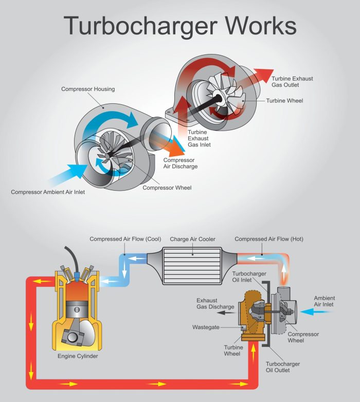
The internal shaft assembly of a forced induction unit spins at speeds exceeding 100,000 RPM in many heavy-duty applications. At these rotational velocities, the journal bearings depend entirely on a thin film of pressurized engine oil to prevent metal-to-metal contact. When oil supply is interrupted—even for a few seconds—the resulting friction generates enough heat to weld bearing surfaces together, scoring the shaft and destroying the cartridge assembly.
Oil starvation is consistently ranked as the number one cause of premature turbo failure across all diesel engine platforms. The root causes of inadequate lubrication include clogged oil feed lines, collapsed oil supply hoses, low oil level in the crankcase, or a malfunctioning oil pump. Each of these conditions creates a situation where the bearing system cannot maintain the hydrodynamic film required for safe operation.
How Oil Contamination Accelerates Wear
Even when oil flow volume is adequate, contaminated lubricant acts as a slow-acting abrasive that gradually erodes bearing surfaces. Diesel engine oil accumulates soot, metalite particles, coolant traces, and fuel dilution over its service interval. When oil change intervals are extended beyond manufacturer recommendations—a common cost-cutting practice in fleet operations—contamination levels rise dramatically.
Soot particles as small as 5 microns can scratch journal bearing surfaces, increasing clearances and allowing shaft wobble to develop. Over time, this progressive wear leads to seal leakage, oil consumption through the compressor housing, and ultimately catastrophic bearing seizure. Studies from major engine manufacturers indicate that extending oil drain intervals by just 20% beyond specification can reduce bearing life by up to 40%.
Signs of Oil-Related Turbo Damage
- Blue or gray exhaust smoke, especially at idle or low load
- Oil pooling in the intercooler or intake manifold
- Scoring marks visible on the shaft when the unit is removed
- Darkened or coked oil residue inside the bearing housing
- Low oil pressure warnings coinciding with reduced boost
Preventive Actions for Oil Starvation
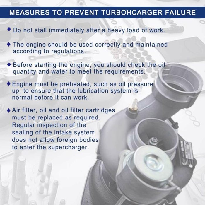
Maintain strict oil change intervals using the correct viscosity grade specified for your engine platform. Inspect oil feed and drain lines during every major service event. Replace oil filters at recommended intervals and use high-quality filtration media rated for diesel soot loading. After any engine work that disrupts oil supply, pre-lube the turbo system before starting the engine by cranking without fuel injection until oil pressure registers.
For fleets operating in extreme conditions—high ambient temperatures, frequent stop-start cycles, or dusty environments—consider shortening oil drain intervals by 15-25% compared to standard highway schedules. The incremental cost of more frequent oil changes is insignificant compared to a $4,000+ turbo replacement plus associated downtime losses.
2. Foreign Object Ingestion
Compressor Side (Intake) Damage
The compressor wheel sits directly downstream of the air filtration system, spinning at tip speeds approaching the speed of sound. Any solid object that bypasses the air filter—a loose hose clamp, a piece of shop rag left during maintenance, or debris from a deteriorating intake hose—will impact the aluminum compressor blades with devastating force.
Even small particles create a chain reaction. An initial nick on one blade creates a vibration imbalance. That imbalance accelerates bearing wear, which increases shaft play, which allows the compressor wheel to contact the housing wall. What started as a 2mm piece of debris can destroy a $2,500 component within minutes of operation. This is a well-documented failure mode that technical support teams encounter frequently when diagnosing returned units.
Turbine Side (Exhaust) Damage
The turbine wheel operates in the exhaust gas stream where temperatures exceed 700°C in many heavy-duty diesel applications. Foreign objects on the hot side typically originate from within the engine itself—broken valve tips, carbon deposits that break free from the exhaust manifold, failed gasket material, or fragments from a deteriorating diesel particulate filter (DPF) substrate.
Turbine wheel damage from exhaust-side debris is particularly insidious because the Inconel alloy blades are designed to withstand extreme heat but are relatively brittle under impact loading. A single fragment strike can fracture a blade root, sending additional fragments downstream and creating a cascade failure that may also damage the exhaust aftertreatment system.
Common Sources of Foreign Object Ingestion
| Debris Source | Side Affected | Typical Cause | Prevention Method |
|---|---|---|---|
| Loose fasteners | Compressor (intake) | Improperly secured clamps during service | Torque all intake clamps to spec; inspect after service |
| Shop debris (rags, tools) | Compressor (intake) | Items left in intake tract during maintenance | Implement foreign object prevention protocols |
| Degraded air filter media | Compressor (intake) | Over-extended filter service life | Replace filters per OE schedule; inspect housing seals |
| Carbon buildup fragments | Turbine (exhaust) | Excessive idle time; poor combustion | Periodic high-load operation; fuel system maintenance |
| Failed exhaust valve fragments | Turbine (exhaust) | Valve seat recession or fatigue cracking | Valve adjustment per schedule; compression testing |
| DPF substrate breakdown | Turbine (downstream effects) | Thermal shock from failed regeneration cycles | Monitor DPF pressure differential; proper regen management |
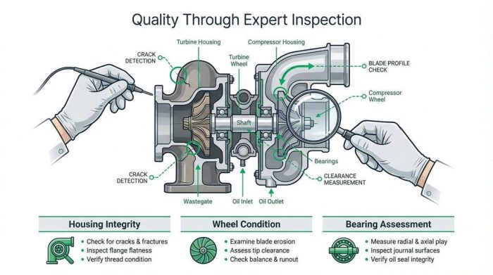
Inspection Protocol After Suspected FOD
If foreign object damage is suspected, never simply replace the turbo unit without identifying and eliminating the source. Remove the intake and exhaust connections and inspect both wheel assemblies with a borescope or visual inspection. Check for corresponding damage upstream (intake system) or upstream exhaust components. Failing to address the root cause will result in immediate repeat failure of the replacement unit.
3. Overheating / Excessive Exhaust Gas Temperature (EGT)
How Thermal Stress Destroys Turbo Components
Heavy-duty diesel engines can produce exhaust gas temperatures exceeding 750°C under full load conditions. The turbine housing, wheel, and shaft assembly are engineered to handle these temperatures during normal operation. However, when EGT rises beyond design limits—due to fuel system problems, restricted airflow, or sustained overloading—thermal damage accumulates rapidly.
Excessive heat causes several simultaneous failure mechanisms. The turbine wheel alloy loses tensile strength, making it susceptible to creep deformation and blade cracking. Oil within the bearing housing carbonizes (cokes), forming hard deposits that restrict oil flow passages and act as abrasives against bearing surfaces. The heat-shield and seal components lose their designed clearances as thermal expansion exceeds tolerance ranges.
Root Causes of Excessive EGT
Injector problems rank among the most frequent causes of elevated exhaust temperatures. A sticking injector that delivers too much fuel, or one with a degraded spray pattern, creates localized combustion hot spots that drive EGT spikes well beyond normal limits. Restricted airflow from a clogged charge air cooler, collapsed intake hose, or malfunctioning variable geometry vane mechanism will also push temperatures higher as the engine runs in an over-fueled condition relative to available air.
Operational factors matter significantly as well. Sustained steep-grade climbing with heavy loads, especially in high ambient temperatures, pushes the entire powertrain toward thermal limits. Drivers who fail to downshift appropriately or who maintain full throttle applications beyond what the engine cooling system can manage create conditions where cumulative thermal damage occurs even when no single event exceeds absolute limits.
The Critical Shutdown Procedure Problem
One of the most damaging yet easily preventable thermal events occurs at engine shutdown. When a heavily-loaded engine is shut down immediately after a sustained high-power run, the exhaust system retains enormous heat energy. Oil flow to the bearing housing ceases immediately, but the turbine shaft, housing, and surrounding components remain at extreme temperatures. Residual heat soaks into the stagnant oil, carbonizing it within the bearing passages.
This "heat soak" coking phenomenon is well-documented in all heavy-duty engine platforms. The solution is simple: allow the engine to idle for 3-5 minutes before shutdown after any extended high-load operation. This cool-down period allows the oil to carry heat away from the bearing housing and reduces the turbo shaft temperature to safe levels before flow ceases. Many modern trucks include automatic idle-down timers for this purpose, but they can be overridden by drivers under time pressure.
Thermal Damage Indicators
- Turbine wheel discoloration (blue/purple tinting beyond normal straw color)
- Coked oil deposits visible in the oil drain passage
- Warped or cracked turbine housing
- Shaft seal deterioration allowing exhaust gases into the oil system
- Heat-related fatigue cracks at blade roots
- Exhaust manifold or up-pipe gasket failures from sustained over-temperature
4. Excessive Shaft Play / Bearing Failure
Understanding Bearing Design in Forced Induction Systems
The rotating assembly in a heavy-duty forced induction unit is supported by a precisely engineered bearing system—typically full-floating journal bearings and a thrust bearing that controls axial movement. These components operate within extremely tight tolerances. Radial shaft play on a new unit is typically specified at 0.03-0.06mm, while axial (end-play) clearance falls between 0.025-0.075mm depending on the specific model.
When bearing surfaces wear beyond specification, the resulting excessive shaft play allows the compressor and turbine wheels to contact their respective housings. This creates the distinctive "turbo whine" or grinding sound that drivers often notice as the first symptom of impending failure. By the time audible contact is occurring, the bearing damage is already advanced and replacement is typically the only viable repair path.
Causes of Premature Bearing Wear
Beyond the oil-related causes discussed earlier, bearing failure can result from several mechanical conditions. Compressor surge—caused by rapid throttle closure or boost controller malfunction—subjects the thrust bearing to repeated axial shock loads that exceed design capacity. The product category system involved in boost regulation must function correctly to prevent these damaging pressure reversals.
Vibration from engine misfires, drivetrain imbalances, or even worn engine mounts can transmit damaging cyclic loads to the turbo bearing system. The transmission input shaft and its associated components can generate torsional vibrations that propagate through the engine block to the exhaust manifold and turbo mounting flange. Similarly, a worn or damaged flywheel creates speed fluctuations at the crankshaft that translate into exhaust pulse irregularities affecting turbine loading.
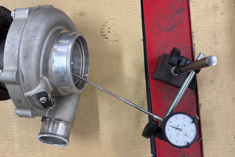
Measuring Shaft Play: A Diagnostic Checklist
| Measurement Type | Acceptable Range | Replacement Threshold | Tool Required |
|---|---|---|---|
| Radial play (side-to-side) | 0.03 – 0.06 mm | > 0.08 mm | Dial indicator with magnetic base |
| Axial play (in-out) | 0.025 – 0.075 mm | > 0.10 mm | Dial indicator or feeler gauge |
| Compressor wheel-to-housing clearance | No contact marks visible | Any rub marks | Visual / borescope inspection |
| Turbine wheel-to-housing clearance | No contact marks visible | Any rub marks | Visual inspection (remove downpipe) |
How to Tell If Your Turbocharger Is Failing
On vehicles equipped with exhaust gas temperature sensors and boost pressure gauges (most modern heavy-duty trucks include these in the ECM data stream), trend monitoring provides early detection capability. A gradual decline in peak boost at the same RPM and load condition, or EGT values trending upward without changes in driving patterns, both signal bearing degradation that warrants physical inspection.
5. Improper Installation or Misalignment
Critical Installation Errors That Guarantee Early Failure
A significant percentage of "warranty" failures are actually caused by installation errors during replacement. The forced induction unit must be installed with precise attention to oil line routing, gasket sealing surfaces, and mounting flange alignment. Even minor deviations from correct procedure can set the replacement unit on a path toward premature failure.
The most critical installation error is failure to pre-lubricate the bearing system before first start. New or remanufactured units ship with a protective coating on internal surfaces, but this is not sufficient lubrication for initial operation. Before connecting the oil feed line, the bearing housing should be primed with clean engine oil through the oil inlet port. Starting a dry unit even briefly can score bearing surfaces within the first few revolutions.
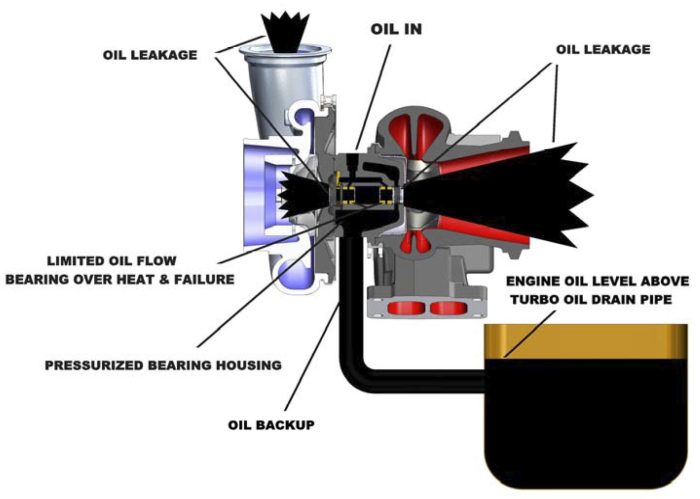
Oil Feed and Drain Line Issues
The oil drain line requires particular attention during installation. This line relies on gravity to return oil from the bearing housing to the crankcase. If the drain line is kinked, restricted, routed uphill at any point, or connected to a crankcase port that experiences positive pressure, oil will back up in the bearing housing. Backed-up oil floods the seal areas and is forced past the compressor and turbine seals into the intake and exhaust systems.
Oil feed lines that are reused without proper cleaning may contain carbon deposits or debris from the previous failed unit. This contamination will immediately compromise the new bearing system. Always replace flexible oil feed lines and thoroughly flush rigid lines with solvent when installing a replacement turbo. Verify feed line banjo bolt orifice sizes match the original specification—an incorrect orifice restricts flow and causes oil starvation.
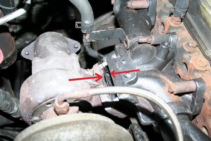
Gasket and Flange Alignment Concerns
The exhaust manifold-to-turbo flange joint must seal completely against exhaust gas leakage. Warped flanges—common after a thermal event that caused the original failure—must be resurfaced or replaced. The friction material in gasket compounds can deteriorate if over-torqued or unevenly clamped, creating leak paths that allow hot exhaust to impinge on oil lines or electrical harnesses.
Similarly, the compressor outlet connection to the charge air cooler piping must be properly aligned and sealed. Any air leak between the compressor and the engine intake reduces system efficiency, forces the turbo to work harder to maintain commanded boost levels, and can introduce unfiltered air containing contaminants that erode compressor components. Trusted suppliers from the product category brand lineup provide complete gasket kits matched to specific applications, ensuring proper sealing without improvisation.
Installation Best Practices Checklist
- Inspect the mounting flange for warpage using a straight edge and feeler gauge
- Clean all mating surfaces of old gasket material and carbon deposits
- Prime the bearing housing with clean engine oil before connecting feed lines
- Install new oil feed and drain lines (or thoroughly flush and inspect existing lines)
- Verify oil drain line routing has continuous downhill grade with no restrictions
- Hand-spin the shaft assembly to verify free rotation before final assembly
- Torque all fasteners to specification in the correct sequence
- Verify all intake piping connections are properly sealed and clamped
- Crank engine without fuel (disconnect injection signal) until oil pressure registers
- Start engine and idle for 3-5 minutes while checking for leaks before loading
6. Exhaust Gas Leakage or Blockage
How Exhaust Leaks Reduce Turbo Performance
Exhaust gas leakage upstream of the turbine inlet represents lost energy. The turbine wheel relies on the full volume and velocity of exhaust flow to generate the rotational energy needed to drive the compressor side. Even a small leak at the exhaust manifold or up-pipe joint reduces the effective drive pressure reaching the turbine, resulting in lower boost levels, sluggish response, and the engine management system compensating by injecting more fuel to maintain power demands.
This compensating behavior creates a vicious cycle. More fuel means higher EGT, which accelerates thermal degradation of both the exhaust system components and the turbo itself. Meanwhile, the leaked exhaust gases—at temperatures exceeding 600°C—can heat-damage surrounding components including wiring harnesses, coolant hoses, and brake lines routed nearby. In severe cases, exhaust leaks near the oil feed line can heat the oil to coking temperatures before it even enters the bearing housing.
Exhaust Backpressure and Blockage Effects
While leaks reduce drive pressure, blockages downstream of the turbine create the opposite problem—excessive backpressure. A clogged diesel particulate filter, collapsed exhaust pipe, or restricted catalytic converter prevents exhaust gases from exiting the system efficiently. This creates a pressure buildup between the turbine outlet and the restriction point, forcing the turbine to work against elevated backpressure rather than flowing freely.
Excessive backpressure increases the pressure differential across the turbine shaft seals, pushing exhaust gases past the seal into the bearing housing. This contamination accelerates oil degradation and can introduce abrasive soot particles directly into the lubrication system. Simultaneously, the engine must generate higher exhaust pressure to overcome the restriction, driving up EGT and further stressing thermal components throughout the system.
Diagnosing Exhaust System Issues
A backpressure test using a simple pressure gauge connected to a port upstream of the suspected restriction can quickly identify blockage issues. Most heavy-duty diesel engines should show less than 3 psi of backpressure at rated speed and load. Values exceeding 5 psi indicate a significant restriction requiring immediate attention. Modern ECM systems monitor DPF differential pressure and will set fault codes when backpressure exceeds programmed limits.
For leak detection, a visual inspection while the engine runs under load often reveals exhaust staining—black soot deposits—around leaking joints. Alternatively, a smoke test with the exhaust outlet blocked can pressurize the system and reveal leaks at gasket joints, cracked manifolds, or deteriorated flex couplings. Any leak found should be repaired immediately to restore full energy delivery to the turbine inlet and protect surrounding components from thermal damage.
Common Exhaust System Failure Points
| Component | Failure Mode | Effect on Turbo System | Inspection Interval |
|---|---|---|---|
| Exhaust manifold gaskets | Thermal fatigue cracking | Reduced turbine drive energy; localized heating | Every 50,000 miles or annual |
| Up-pipe bellows/flex joint | Fatigue cracking from thermal cycling | Major energy loss; audible exhaust leak | Visual check every service |
| DPF substrate | Plugging or thermal cracking | Excessive backpressure; seal damage | Monitor differential pressure continuously |
| Exhaust manifold (cast iron) | Warpage or cracking at cylinder ports | Uneven exhaust pulse delivery; energy loss | Every 100,000 miles or when symptoms appear |
| V-band clamps | Loosening from thermal cycling | Joint separation; complete pressure loss | Retorque every 25,000 miles |
7. Lack of Regular Maintenance
The Cumulative Effect of Deferred Maintenance
No single maintenance omission typically causes immediate turbo failure. Instead, deferred maintenance creates a cascade of marginal conditions that collectively overwhelm the system's tolerance for imperfection. Extended oil change intervals combine with a slightly restricted air filter and a minor exhaust leak to push operating conditions beyond acceptable limits—even though each individual deviation might be survivable in isolation.
Fleet operations data shows a clear correlation between maintenance discipline and forced induction system longevity. Vehicles maintained strictly per manufacturer schedules consistently achieve 300,000-500,000 miles of turbo life. Those with inconsistent maintenance histories frequently experience failures between 100,000-200,000 miles—representing a 50-60% reduction in component service life and dramatically increased lifecycle cost per mile.
Critical Maintenance Items That Directly Affect Turbo Life
Air filtration is the first line of defense against compressor-side damage. A heavy-duty diesel engine consumes approximately 8,000-12,000 cubic feet of air per hour at highway speeds. Every particle that passes through a degraded filter element becomes a potential projectile aimed at the compressor wheel. Filter replacement intervals must account for actual operating conditions—dusty environments, construction zones, or gravel roads demand inspection and replacement far more frequently than highway-only applications.
Charge air cooler (intercooler) maintenance is frequently overlooked but directly impacts boost system health. External fin fouling from road debris, insects, and mud reduces cooling efficiency, raising intake manifold temperatures and forcing the engine to work harder. Internal contamination from oil carryover (often an early sign of seal wear) restricts airflow and creates turbulence that reduces volumetric efficiency. Periodic removal and cleaning—both internally and externally—should be part of any comprehensive preventive maintenance program.
Maintenance Schedule for Maximum Turbo Longevity
| Maintenance Item | Highway Schedule | Severe Duty Schedule | Impact on Turbo Life |
|---|---|---|---|
| Engine oil and filter change | Every 25,000 miles | Every 15,000 miles | Direct bearing lubrication quality |
| Air filter inspection/replacement | Every 30,000 miles | Every 10,000-15,000 miles | Compressor wheel protection from debris |
| Intake system inspection (hoses, clamps) | Every 50,000 miles | Every 25,000 miles | Prevents unfiltered air and FOD ingestion |
| Charge air cooler cleaning | Every 100,000 miles | Every 50,000 miles | Maintains cooling efficiency and airflow |
| Exhaust system inspection | Every 50,000 miles | Every 25,000 miles | Detects leaks and backpressure issues early |
| Turbo shaft play measurement | Every 150,000 miles | Every 100,000 miles | Early detection of bearing wear trends |
| Oil feed/drain line inspection | Every 100,000 miles | Every 50,000 miles | Ensures unobstructed oil flow to bearings |
| Coolant system service | Per manufacturer interval | Per manufacturer interval | Prevents overheating that raises EGT |
The Role of Driver Behavior in Maintenance Outcomes
Even the most rigorous maintenance program cannot fully compensate for abusive driving practices. Drivers who consistently operate at full throttle without adequate warm-up periods, who shut down immediately after high-load operation without cool-down idle time, or who ignore dashboard warnings about filter restrictions or high EGT will shorten turbo life regardless of how well the vehicle is maintained mechanically.
Fleet managers should invest in driver education that specifically addresses turbo-friendly operating practices. Telematics systems that monitor idle-before-shutdown duration, EGT exceedances, and over-boost events can identify drivers whose habits are costing the fleet in premature component failures. The combination of proper maintenance and educated operators represents the most cost-effective strategy for maximizing forced induction system longevity.
How to Prevent Turbocharger Failure: A Comprehensive Strategy
Pre-Trip and Post-Trip Inspection Protocols
Incorporating turbo-specific checks into daily pre-trip and post-trip inspections catches developing problems before they become catastrophic failures. During pre-trip, listen for unusual sounds during cold start—grinding, whining, or excessive whooshing that differs from normal spool-up characteristics. Check under the hood for oil wetness around intake piping connections, which may indicate seal leakage from overnight heat-soak oil migration.
Post-trip inspections should include a visual scan for new exhaust staining at manifold and piping joints, verification that no warning lights illuminated during the trip, and notation of any performance changes such as reduced power, excessive smoke, or unusual response characteristics. These observations, documented consistently, create a trend history that enables predictive maintenance decisions.
Oil System Management
Beyond following scheduled oil changes, proactive oil system management includes regular oil analysis sampling. Oil analysis laboratories can detect bearing metals (copper, lead, tin from journal bearings), elevated silicon (indicating air filtration bypass), coolant contamination, and fuel dilution—all conditions that directly threaten turbo bearing life. A quarterly oil sample costs approximately $25-35 and provides early warning of developing problems months before physical symptoms appear.
Choose oil viscosity grades and API/ACEA quality levels that match your engine manufacturer's specifications exactly. Heavy-duty diesel engines with high-pressure common rail injection systems are particularly sensitive to oil quality, as fuel dilution from regeneration events can thin oil viscosity below bearing protection minimums. Monitoring oil level between services and investigating any unexpected consumption helps identify seal issues while they are still minor.
Air Intake System Integrity
The air intake system must maintain perfect sealing from the filter housing to the compressor inlet. Any breach in this sealed path—a cracked hose, loose clamp, deteriorated gasket, or damaged filter housing—allows unfiltered air containing abrasive dust particles direct access to the compressor wheel. In construction, mining, or agricultural environments where airborne particulate density is high, even brief exposure to unfiltered air can cause measurable compressor erosion.
Inspect all rubber and silicone intake hoses for cracking, softening, or collapse during every service event. Pay particular attention to the accordion-style flexible sections that accommodate engine movement—these are stress concentration points that develop cracks from thermal cycling and vibration. The pressure plate and mounting hardware on aftermarket intake components must be verified for proper fit and sealing capability.
Choosing Quality Replacement Components
When replacement becomes necessary, component quality directly determines the lifespan of the new unit. Inferior aftermarket units may use substandard bearing materials, imprecise machining tolerances, or unbalanced rotating assemblies that are destined for early failure regardless of how well they are installed and maintained. Research from fleet maintenance associations indicates that premium replacement components last 2-3 times longer than bargain alternatives when total lifecycle cost is calculated.
Mettlead provides quality components backed by engineering expertise and rigorous testing protocols. Their product line covers major heavy-duty diesel platforms with units that meet or exceed original specifications for balance quality, material composition, and dimensional accuracy. For fleet operators seeking to maximize uptime and minimize repeat failures, investing in properly engineered replacement parts represents the most economical long-term strategy. Learn more about us and our commitment to supporting commercial vehicle maintenance programs.
Expected Service Life Under Proper Conditions
A common question fleet managers ask is how long does a turbocharger last on average in heavy-duty service. Under proper maintenance conditions with appropriate operating practices, quality forced induction units on Class 8 highway trucks typically achieve 400,000-600,000 miles of service life. Vocational applications with more severe duty cycles (frequent stop-start, high idle time, extreme temperatures) may see service lives of 200,000-350,000 miles.
These figures assume strict adherence to maintenance schedules, quality lubricant usage, proper installation procedures, and driver training on thermal management practices. Vehicles that consistently fall short of these longevity benchmarks likely have an underlying systemic issue—whether maintenance-related, operational, or installation-related—that warrants investigation rather than simply replacing the failed unit and accepting repeat failures as normal. Review documented cooperative case studies to see how proper component selection and maintenance practices deliver expected service life in real-world fleet operations.
Frequently Asked Questions
What is the most common reason for forced induction failure in diesel trucks?
Oil starvation and contamination account for approximately 38% of premature failures in heavy-duty applications. This includes insufficient oil supply from blocked feed lines, oil that has degraded beyond its protective capability due to extended service intervals, and contaminated lubricant carrying abrasive particles into the bearing system. Maintaining strict oil change schedules with quality lubricants matched to your engine's specifications is the single most effective protective measure you can implement.
How can I detect early signs of boost system problems before complete failure?
Watch for these progressive warning signs: increasing oil consumption without visible external leaks, blue or gray exhaust smoke particularly at idle or during deceleration, a gradual decline in engine responsiveness or power output, unusual whistling or whining sounds from the engine bay that change with RPM, and higher-than-normal exhaust gas temperatures at the same load conditions. Any of these symptoms warrants immediate inspection—early detection typically allows for planned replacement before catastrophic failure causes secondary damage to downstream components.
Does shutting down the engine immediately after highway driving damage the turbo?
Yes, immediate shutdown after sustained high-load operation is one of the most damaging yet easily preventable practices. When the engine stops, oil flow ceases immediately while the rotating assembly and housing remain at extreme temperatures. This residual heat carbonizes the stagnant oil within the bearing passages, creating hard deposits that restrict lubrication on the next start cycle. Always idle for 3-5 minutes after extended highway driving or heavy load operation to allow the oil to carry heat away from the bearing housing before flow stops.
How often should the forced induction system be inspected on a heavy-duty truck?
At minimum, perform a visual inspection of all intake and exhaust connections during every preventive maintenance service (typically every 25,000 miles or quarterly for most fleet operations). Measure shaft play every 100,000-150,000 miles depending on duty cycle severity. Inspect oil feed and drain lines every 50,000-100,000 miles. Monitor boost pressure and EGT trends continuously through the ECM data system. Vehicles operating in severe conditions—construction, mining, frequent stop-start urban delivery—should follow the more aggressive inspection intervals
Can a forced induction system be repaired, or must it always be replaced?
In many cases, the complete cartridge assembly (center housing rotating assembly or CHRA) can be replaced while reusing the compressor and turbine housings, provided those housings are not damaged, warped, or cracked. This rebuild approach costs 40-60% less than complete unit replacement. However, it requires accurate diagnosis to ensure housing integrity, correct clearance specifications during reassembly, and proper balancing of the rotating assembly. For fleets without in-house capability, exchange programs offering remanufactured units with warranty coverage provide the best balance of cost, quality, and convenience. Professional suppliers maintain comprehensive inventory across all major heavy-duty engine platforms to minimize downtime during replacement.
Conclusion: Protecting Your Fleet Investment
Forced induction system failures in heavy-duty diesel trucks are overwhelmingly preventable. The evidence consistently shows that proper oil management, air filtration integrity, thermal discipline, correct installation procedures, and regular system inspections can extend component life to 400,000 miles or beyond—while neglecting these fundamentals routinely cuts service life by half or more.
The most effective protection strategy combines three elements: a disciplined maintenance program that addresses all lubrication, filtration, and exhaust system requirements on schedule; driver training that emphasizes proper warm-up, cool-down, and load management practices; and quality replacement components engineered to meet the demanding requirements of heavy-duty commercial service when replacement eventually becomes necessary.
Investing in prevention consistently delivers 5:1 or greater return compared to accepting reactive failure as normal operating cost. Every dollar spent on proper maintenance, quality parts, and operator education comes back multiplied in reduced downtime, eliminated emergency repair premiums, and extended intervals between major component replacements. For heavy-duty fleets committed to operational excellence, turbo system longevity is not a matter of luck—it is a predictable outcome of disciplined engineering practice.