
7 Easy Steps to Replace a Brake Drum Like a Professional
Why Replacing a Worn Brake Drum Matters for Safety
Whether you're a weekend mechanic or fleet technician, performing this replacement correctly saves money and time. This guide walks you through every stage with precision from over fifteen years of hands-on brake system experience. We cover not only the mechanical procedure but also the diagnostic reasoning, safety protocols, and post-installation verification that separates amateur attempts from professional-grade work.
The rear drum-style braking assembly remains common on modern vehicles despite the prevalence of disc systems on front axles. Manufacturers continue using this design on rear wheels for several compelling reasons: lower manufacturing cost, superior parking brake integration, reduced maintenance frequency compared to rear disc setups, and adequate performance for the lighter braking loads rear axles typically handle (most vehicles distribute 60–70% of braking force to the front). Understanding these engineering decisions helps you appreciate why proper maintenance of these components remains essential for vehicle safety.
Understanding How Drum-Style Braking Systems Work
Before diving into the replacement procedure, understanding the operating principles helps you diagnose problems and perform the work more effectively. A drum-style rear braking assembly converts kinetic energy into thermal energy through friction between stationary shoes and a rotating cylindrical casting bolted to the wheel hub.
Key Components and Their Functions
The system consists of several integrated components working together:
- Cylindrical casting (drum): The rotating element bolted to the hub, providing the friction surface against which shoes press. Cast from gray iron (typically SAE J431 Grade G3000 or G3500) for optimal heat dissipation and wear resistance.
- Brake shoes: Curved metal platforms lined with friction material (semi-metallic, organic, or ceramic compounds). One shoe is the "leading" or "primary" shoe; the other is the "trailing" or "secondary" shoe.
- Wheel cylinder: A hydraulic actuator mounted on the backing plate that pushes shoe ends outward when the driver presses the brake pedal.
- Backing plate: A stamped steel plate bolted to the axle housing that supports all brake components and acts as a dust shield.
- Return springs: Heavy-duty springs that retract shoes away from the friction surface when hydraulic pressure releases.
- Hold-down springs: Keep shoes positioned flat against the backing plate during operation.
- Self-adjuster mechanism: Automatically compensates for shoe wear by incrementally extending a star-wheel adjuster during reverse braking applications.
- Parking brake mechanism: A cable-actuated lever that mechanically forces shoes outward independent of hydraulic pressure.
The Servo (Self-Energizing) Effect
Drum-type systems benefit from a mechanical advantage called servo action. When the leading shoe contacts the rotating surface, friction drags it further into engagement, amplifying the applied force. This self-energizing effect means drum systems produce substantial stopping force with relatively low hydraulic pressure — one reason they remain effective for rear applications despite their thermal limitations compared to ventilated disc designs.
However, this same characteristic makes them sensitive to friction coefficient changes. Contamination from brake fluid, axle grease, or moisture dramatically reduces the servo effect, which is why maintaining clean, uncontaminated friction surfaces during service is critical.
Heat Management Challenges
The enclosed design limits airflow compared to disc systems. Heat generated during braking must conduct through the casting walls and radiate from the external surface. This thermal limitation explains why repeated heavy braking — such as long downhill descents — causes drum-type systems to experience fade before disc systems do. The iron casting expands outward as temperature rises, moving the friction surface away from the shoes and requiring greater pedal effort. Understanding this behavior helps you appreciate why proper material composition and dimensional specifications matter so much in replacement parts.
Common Brake Drum Failures: Causes and Warning Signs
Understanding why these components fail helps you diagnose problems accurately and prevent repeat failures. Each failure mode has distinct causes, symptoms, and remediation approaches.
Scoring and Grooves
Deep grooves on the inner contact surface result from worn lining left in service too long. Once friction material wears completely, the metal backing plate cuts channels into the casting. If grooves exceed 0.060 inches in depth, the component must be replaced entirely. Minor scoring under this threshold can sometimes be addressed through resurfacing on a brake lathe, but only if the resulting diameter remains within maximum specification.
Scoring accelerates wear on new shoes installed against a grooved surface because contact area is reduced. The raised ridges between grooves concentrate pressure, causing premature wear patterns that mirror the original damage. This is why installing new shoes against a scored surface without resurfacing guarantees shortened shoe life and potentially uneven braking.
Out-of-Round (Ovality)
Repeated heat cycling distorts the casting into a slightly oval shape, causing pedal pulsation. NHTSA notes that out-of-round conditions exceeding 0.006 inches warrant replacement. This is common in vehicles that haul heavy loads or descend steep grades frequently.
The mechanism works as follows: during heavy braking, the casting heats unevenly due to slight variations in shoe contact, material thickness, or cooling rates. Iron expands in heated areas and contracts as it cools. Over hundreds of heat cycles, these micro-distortions accumulate into measurable ovality. The driver notices this as a rhythmic surge in pedal resistance during stops — the shoes alternately contact and lose contact with the non-circular surface as it rotates.
Heat Spots and Hardened Areas
Localized overheating creates hard spots that resist normal wear, appearing as bluish-purple discolorations on the friction surface. These form when temperatures exceed approximately 1,400°F locally, transforming the pearlitic gray iron microstructure into martensite or cementite — much harder phases that cannot be resurfaced effectively because they damage lathe cutting tools and create further surface irregularities.
Hard spots cause grabbing, vibration, and accelerated wear on opposing friction material. Replacement ensures uniform material properties across the entire braking surface. Attempting to resurface a casting with hard spots typically produces a temporarily smooth surface that quickly develops raised areas as the harder regions resist wear while surrounding softer material wears normally.
Cracking
Thermal stress cracks radiate outward from the open edge. Any crack extending more than halfway across the contact surface requires immediate replacement due to risk of catastrophic failure. Cracks typically start at the open edge because this area experiences the greatest thermal stress — it's thinner and heats/cools faster than the closed end near the hub.
Two types of cracking occur: heat checking (a network of fine surface cracks similar to dried mud) and through-cracks (deep fissures penetrating significant material depth). Heat checking alone may not require immediate replacement if the network is superficial, but it indicates the component has experienced severe thermal stress and warrants careful monitoring. Through-cracks always require immediate replacement regardless of length or depth.
Tools and Materials for Brake Drum Replacement
Having the correct tools prepared before starting prevents mid-job frustration and ensures safe completion. Nothing derails a brake job faster than discovering you need a specialty tool with the vehicle on jack stands and wheels removed. Organize everything within arm's reach before loosening the first lug nut.
Essential Tools
- Floor jack (minimum 2-ton rating) and jack stands (pair)
- Wheel chocks, lug wrench or impact wrench
- Rubber mallet or brass drift
- Drum puller (recommended for seized components)
- Brake spoon or star-wheel adjuster tool
- Needle-nose pliers and flat-blade screwdriver
- Wire brush and brake parts cleaner (non-chlorinated)
- Digital caliper or inside micrometer
- Torque wrench (covering 75–140 ft-lbs for lug nuts)
- Safety glasses, nitrile gloves, P100-rated dust mask
- Spring removal/installation pliers (specifically designed for brake springs)
- Brake bleeder wrench set
- Magnetic tray for small fasteners
- Penetrating oil (PB Blaster, Kroil, or similar)
- Propane or MAP gas torch (for seized components)
- Shop light or headlamp for visibility
- Catch pan for brake fluid
Replacement Parts
- New rear braking assembly matched to your vehicle (always replace as axle pair)
- New brake shoes (replace simultaneously for optimal bedding)
- Return springs and hold-down hardware kit (never reuse springs)
- Wheel cylinder (if leaking or over 100,000 miles)
- Brake fluid (DOT 3 or DOT 4 as specified by manufacturer)
- Anti-seize compound and high-temperature brake grease
- Replacement retaining screws (often corroded beyond reuse)
- Self-adjuster cable and guide (if worn or stretched)
Optional But Recommended
- Dial indicator for measuring hub runout
- Smartphone or camera for documenting assembly before disassembly
- Service manual specific to your vehicle (torque specs, adjuster direction)
- Second set of jack stands (for working on both sides simultaneously)
- Creeper or foam kneeling pad for comfort during extended work
Investing in quality parts from a trusted product category brand ensures proper fitment and longevity. Cheap aftermarket castings often have inconsistent metallurgy, poor balance, and dimensional variations that cause noise, vibration, and premature wear.
Pre-Work Preparation and Vehicle Assessment
Before raising the vehicle, perform a thorough assessment that helps you plan the job accurately, identify potential complications, and ensure you have all necessary parts.
Gathering Vehicle Information
Locate the following specifications before beginning:
- Maximum internal diameter: Cast into the exterior of the existing component, or found in service manual
- Lug nut torque specification: Varies by vehicle — never guess
- Brake fluid type: DOT 3, DOT 4, or DOT 5.1 as specified
- Adjuster rotation direction: Left and right sides often differ
- Parking brake cable routing: Some designs require cable disconnection for removal
Visual Inspection Before Lifting
With the vehicle still on the ground, check the following:
- Brake fluid reservoir level — if very low, expect significant shoe wear or a leak
- Rear brake hose condition — cracks, bulges, or wetness indicate replacement needed
- Parking brake operation — should engage within 3–5 clicks and hold on a slight grade
- Tire condition — uneven wear patterns may indicate a dragging brake
- Road test observations — note any pulling, pulsation, noise, or pedal issues
Workspace Preparation
Set up your workspace for efficiency and safety:
- Work on a flat, level concrete surface — never gravel, grass, or sloped driveways
- Ensure adequate ventilation — brake dust contains particulates harmful to lungs
- Position lighting to eliminate shadows inside the assembly
- Lay out tools in the order you'll use them
- Have a trash container ready for contaminated parts and soiled rags
- Keep a fire extinguisher accessible when using a torch
Step 1: Safely Lift and Secure the Vehicle
More garage injuries result from improperly supported vehicles than any other cause during DIY brake work. Work on a flat concrete surface with adequate lighting and ventilation. This step deserves extra attention and deliberation — rushing the setup puts you at risk throughout the entire procedure.
Engaging Safety Measures
- Place transmission in Park (automatic) or first gear (manual).
- Set the parking brake firmly.
- Place wheel chocks against front tires on both sides — use substantial chocks, not small rubber wedges.
- Loosen rear lug nuts one-quarter turn while weight keeps everything stable. Use a breaker bar for leverage if needed.
- Verify the floor jack is rated for your vehicle's weight — most passenger vehicles weigh 3,000–5,500 lbs total.
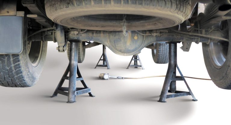
Lifting Procedure
Raise the vehicle until the rear tire clears ground by 3–4 inches. Position jack stands under frame rails or axle at designated support points — never under body panels, suspension components, or the differential housing on unibody vehicles. Lower the jack until weight rests entirely on stands. Test stability by pushing firmly at multiple points — any wobble means repositioning is needed.
Never work under a vehicle supported only by a jack. Hydraulic jacks can fail without warning due to seal leaks, overloading, or accidental valve release. Jack stands are a non-negotiable safety requirement regardless of how "quick" the job seems.
Once securely supported, release the parking brake so the internal mechanism doesn't prevent removal. Note: on some vehicles, you may need to work one side at a time to maintain vehicle stability, especially if working alone.
Working on Both Sides
Since you're replacing components in axle pairs, plan your approach. Two strategies work well:
- Sequential method: Complete one side fully before starting the other. The undisturbed side serves as a reference for spring routing and adjuster orientation.
- Parallel method: Remove both assemblies, clean and inspect simultaneously, then install. Requires good photos and notes since no assembled reference remains.
For first-time technicians, the sequential method is strongly recommended. Having an assembled reference on the opposite side prevents confusion about spring placement and adjuster orientation.
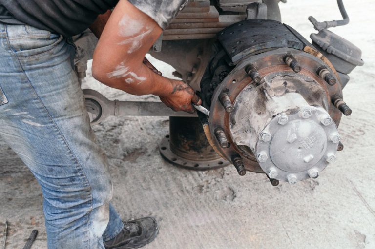
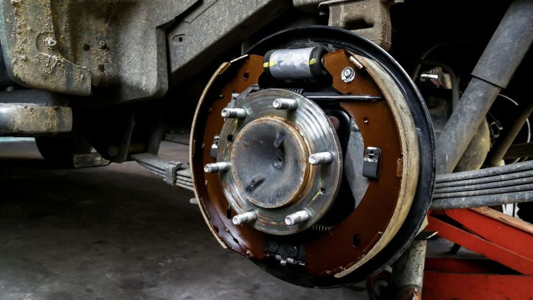
Step 2: Remove the Wheel and Assess External Condition
Finish removing the loosened lug nuts and place them in a magnetic tray — dropped lug nuts have an uncanny ability to roll under vehicles and disappear. Grip the tire at 3 and 9 o'clock and pull straight toward you. If stuck, a few rubber mallet hits onthe back side of the tire breaks corrosion free without damaging the wheel finish.
With the wheel removed, take a moment to observe the overall condition before touching anything. This initial assessment often reveals issues that affect your repair strategy:
- Fluid leaks: Wetness around the wheel cylinder indicates seal failure. Plan to replace the cylinder during this service — contaminated friction material must also be replaced.
- Axle seal leaks: Gear oil weeping past the axle seal contaminates shoes and requires seal replacement before completing brake work.
- Heavy rust on backing plate: Surface rust is normal; heavy flaking or perforation indicates structural compromise.
- Visible damage: Dents, bends, or missing components from road debris impact.
- Brake line condition: Trace the hard line and flexible hose looking for corrosion, kinks, or bulges.
Before touching brake components, examine the area for fluid leaks near the wheel cylinder, heavy rust, and visible damage to the backing plate. A leaking cylinder contaminates shoe material and requires replacement during this service. Document everything you observe — these notes inform parts ordering and help you avoid surprises mid-job.

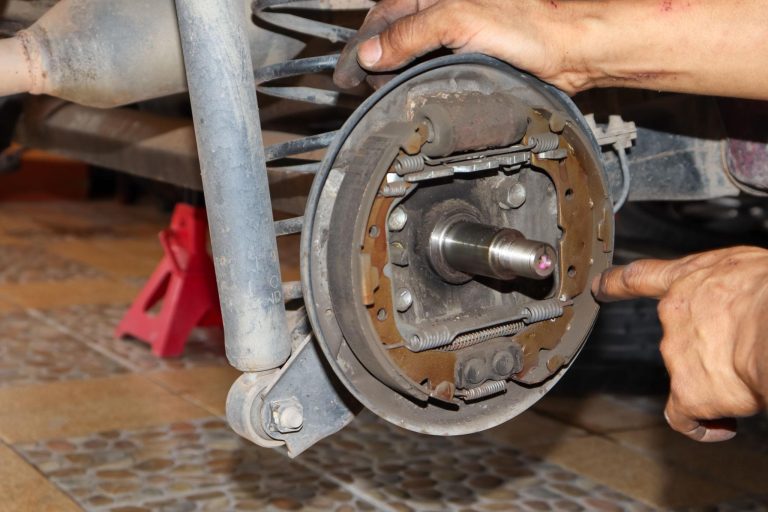
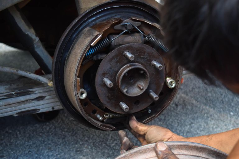
Step 3: Inspect the Rear Drum Assembly Components
Inspect the visible outer surface for cracks, heavy rust, and contact marks. Find the maximum allowable internal diameter cast into the outer surface — you'll need this after removal to determine whether the component has exceeded its wear limit. This number is typically stamped or cast in raised letters on the outer circumference, expressed in millimeters or inches (e.g., "282 mm MAX" or "11.09 IN MAX").
Understanding Maximum Diameter Specifications
The maximum diameter represents the absolute limit beyond which the casting wall becomes too thin to safely contain braking forces and dissipate heat. Operating beyond this specification risks:
- Catastrophic fracture under heavy braking due to insufficient wall thickness
- Excessive thermal expansion causing brake fade at lower temperatures
- Increased stopping distance as shoes cannot maintain full contact
- Accelerated overheating due to reduced thermal mass
Never exceed this specification regardless of how smooth the surface appears. A casting that measures at or near maximum diameter must be replaced even if it shows no visible defects.
Assessing Related Components
- Backing plate: Firmly bolted with no bending or distortion. Check all mounting bolts for tightness. The plate should not flex when pushed.
- Brake lines/hoses: No cracking, bulging, or wetness. Flex the rubber hose gently — if the outer covering cracks or flakes, replace it.
- Axle seal: No gear oil leaking past the seal onto the backing plate interior.
- Hardware: Springs and adjusters free of heavy corrosion. Note the routing and position of each spring.
- Adjuster mechanism: Should be free to rotate. Heavy corrosion here means the self-adjuster hasn't been functioning.
Take several clear photos from different angles before disassembly for reassembly reference. Photograph the spring routing, adjuster cable path, parking brake lever orientation, and overall layout. These photos become invaluable during reassembly when you're trying to remember which spring hooks where.
Documenting Wear Patterns
Before removal, note any unusual wear indicators visible from outside:
| External Indicator | What It Suggests | Additional Inspection Needed |
|---|---|---|
| Brake dust coating evenly distributed | Normal wear pattern | Standard inspection |
| Heavy dust on one area only | Uneven shoe contact | Check for bell-mouth wear |
| Oil or fluid contamination | Seal failure (wheel cylinder or axle) | Identify leak source |
| Metal shavings or flakes | Severe wear — metal-on-metal contact | Expect scoring, possible replacement |
| Rust streaks from weep hole | Wheel cylinder leaking internally | Replace wheel cylinder |
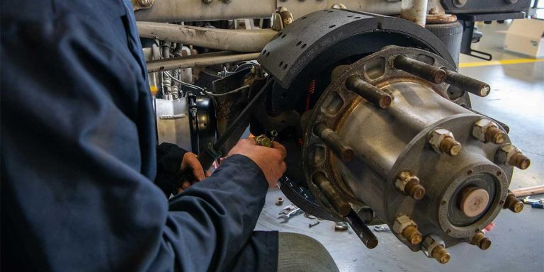
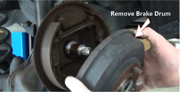
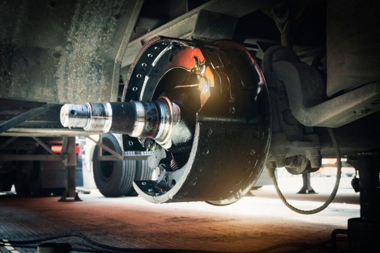
Step 4: Remove the Old Brake Drum
This step often proves most challenging due to corrosion and heat cycling that effectively weld the casting to the hub over years of service. Patience and the correct technique prevent damage to surrounding components. Remove any retaining screws first, applying penetrating oil to stubborn ones.
Why Removal Becomes Difficult
Several factors contribute to a seized casting:
- Corrosion bonding: Rust forms between the hub pilot and the casting bore, creating a mechanical bond that essentially glues the parts together.
- Shoe expansion: If shoes have worn a ridge into the friction surface, they may be expanded beyond that ridge, preventing straight removal.
- Parking brake tension: If the parking brake wasn't fully released, shoes are mechanically held against the surface.
- Road salt and moisture: Vehicles in northern climates or coastal areas accumulate corrosion deposits at every interface.
Removal Techniques (Escalating Order)
- Straight pull: Grasp outer edges and pull firmly while rocking side to side. Often sufficient on vehicles in dry climates or those recently serviced.
- Penetrating oil: Spray around the hub interface where the pilot bore meets the hub centering ring, wait 10–15 minutes. Apply a second application and tap the outer edge with a rubber mallet while pulling.
- Rubber mallet persuasion: Strike alternately at 12, 3, 6, and 9 o'clock positions on the outer face while applying outward pressure. The alternating impacts break corrosion bonds progressively.
- Heat application: Apply propane torch evenly around center hub area, keeping flame moving to avoid localized overheating. Heat expands the casting slightly, breaking the corrosion bond. Allow 2–3 minutes of even heating.
- Threaded puller holes: Many castings have two threaded holes (typically 8mm x 1.25 or 3/8"-16) cast into the face specifically for removal. Thread bolts into these holes and tighten alternately in half-turn increments to press the casting off the hub evenly.
- Three-jaw puller: Grips outer edge while pushing against hub center. Use protective caps on hub studs to prevent thread damage from the puller's center bolt.
If the component starts to move but stops after traveling a short distance, the shoes are likely expanded beyond a wear ridge on the inner surface. Access the star-wheel adjuster through the backing plate slot (an oval hole, often covered by a rubber plug) and retract the shoes by turning the adjuster wheel with a brake spoon until the assembly slides off freely.
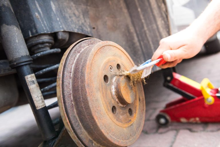
Step 5: Clean, Measure, and Inspect All Parts
With the casting removed, you now have full access to the internal brake assembly and can perform detailed measurements and inspections that determine which components require replacement.
Measuring the Removed Component
| Location | What It Reveals | Acceptable Tolerance |
|---|---|---|
| Open End (vertical) | Bell-mouth wear | Within 0.005–0.006" of center measurement |
| Open End (horizontal) | Ovality at open edge | Within 0.006" of vertical measurement at same location |
| Center (vertical) | Maximum wear diameter | Under max specification cast on component |
| Center (horizontal) | Ovality at center | Within 0.006" of vertical measurement at same location |
| Closed End (vertical) | Barrel wear | Within 0.005–0.006" of center measurement |
| Closed End (horizontal) | Ovality at closed edge | Within 0.006" of vertical measurement at same location |
Record all measurements and compare against the maximum specification. If any single measurement exceeds the maximum, or if resurfacing would push any measurement beyond maximum, the component must be replaced. Even if measurements are within specification, presence of hard spots, through-cracks, or heavy scoring that cannot be cleaned up within 0.060" of cutting typically warrants replacement.
Inspecting Shoes, Cylinder, and Hardware
Shoe friction material should be at least 1/32" above rivet heads (riveted shoes) or 1/16" above the metal backing plate (bonded shoes). Replace if worn below these minimums, contaminated with fluid, cracked, chipped, or glazed to a shiny appearance. Always replace in complete axle sets — never replace just one shoe or one side.
Evaluate the wheel cylinder by carefully peeling back the rubber dust boots at each end. Any moisture, even a slight dampness, means the internal seals have failed and the cylinder requires replacement. Push each piston inward using finger pressure — they should move smoothly without sticking, binding, or requiring excessive force. A piston that won't move likely has internal corrosion or swollen seals from contaminated fluid.
Step 6: Install the New Brake Drum
Reassembling Internal Components
If you replaced shoes, springs, or other internal components, reassemble them before installing the new casting. Work methodically using your reference photos:
- Install the anchor pin and adjuster mechanism: Verify the adjuster is oriented correctly (star wheel facing the correct direction for that side of the vehicle). Left and right adjusters are typically different.
- Position the primary (shorter) shoe: The primary shoe faces the front of the vehicle. Install its hold-down spring and pin.
- Position the secondary (longer) shoe: The secondary shoe faces the rear. Install its hold-down spring and pin.
- Connect the adjuster between shoe bottoms: Ensure the adjuster socket sits properly in each shoe web notch.
- Install return springs: Upper and lower springs pull shoes back toward the anchor and adjuster. Use spring pliers — these springs store significant energy and can cause injury if they slip.
- Install the self-adjuster cable and lever: Route exactly as documented in your photos. The cable connects from the anchor pin, around the secondary shoe, to the adjuster lever.
- Connect the parking brake lever: Ensure the cable has appropriate free play and the lever operates smoothly.
After reassembly, verify shoes are seated flat against backing plate contact pads, springs are properly hooked and not twisted, and the adjuster turns freely in both directions. Pull each shoe outward and release — it should snap back crisply against the adjuster or anchor.
Preparing the New Part
Remove the protective oil coating completely with brake parts cleaner — spray generously inside and out, then wipe with clean shop towels until no residue remains. This coating prevents rust during shipping but would contaminate friction material and reduce braking effectiveness during the break-in period if left in place.
Inspect the new casting for:
- Casting defects (porosity, inclusions, surface irregularities)
- Shipping damage (chips, cracks from impact)
- Dimensional accuracy (measure internal diameter — it should match nominal specification)
- Balance weights (if present, verify they're secure)
- Proper part number verification against your vehicle application
Apply thin anti-seize compound to the hub pilot bore (the center hole that registers on the hub centering ring) to prevent future corrosion bonding. Keep anti-seize away from the internal friction surface and shoe contact area.
Sliding the Component Into Place
Verify shoes are retracted sufficiently by checking that the adjuster is backed off (shoes at minimum extension), then align the casting with hub studs and slide it straight on. It should move freely onto the hub with minimal resistance — slight drag from shoes touching the friction surface is normal, but binding or inability to seat fully indicates a problem.
If resistance is felt:
- Check parking brake is fully released at both the cabin lever and the cable adjustment
- Verify adjuster is backed off completely
- Confirm springs are pulling shoes inward correctly — a displaced spring may hold a shoe outward
- Ensure no tools, hardware, or debris are trapped between shoes and the friction surface
- Verify correct part number — wrong application may have slightly different internal diameter
Never force it on — identify and correct any obstruction first. Forcing a misaligned casting damages hub studs, bends the backing plate, or cracks the casting itself.
Adjusting the Shoes
Proper shoe adjustment ensures immediate braking response while preventing drag. The procedure requires patience and a careful touch:
- Access the star-wheel adjuster through the backing plate slot (remove the rubber plug if present).
- Rotate the star-wheel to expand shoes until the casting locks up completely and cannot be rotated by hand.
- Back off 8–10 clicks until the casting rotates freely with light, even drag.
- Spin several revolutions in each direction — rotation should feel smooth without rhythmic catching, scraping, or heavy spots.
- Verify the self-adjuster mechanism functions by pulling the adjuster cable or lever and confirming the star-wheel advances one notch.
The goal is a barely perceptible drag that indicates shoes are close to the friction surface without actually dragging during driving. Too tight causes overheating; too loose results in excessive pedal travel before braking begins.
Verifying Parking Brake Operation
Before proceeding to wheel installation, confirmthe parking brake lever engages the shoes mechanically by pulling the cable at the backing plate. The lever should move freely, and applying the cabin parking brake handle should visibly spread the shoes outward. If the cable feels slack or the lever doesn't actuate, adjust cable tension at the equalizer (located under the vehicle, typically near the rear axle) until 3–5 clicks of handle travel locks the shoes firmly against the friction surface.
Release the parking brake completely after verification and confirm the casting returns to free rotation. A parking brake that doesn't fully release causes constant drag, overheating, and rapid wear of new components.
Step 7: Reinstall the Wheel and Test Your Work
Mounting and Torquing
Thread all lug nuts by hand first to prevent cross-threading, then snug in a star pattern using your lug wrench. Do not fully torque while the vehicle is on jack stands — the wheel will simply spin. Lower the vehicle until the tire contacts ground without bearing full weight (tire compressed slightly but vehicle still partially supported). Torque to manufacturer specification using a calibrated torque wrench:
| Vehicle Type | Typical Torque (ft-lbs) | Notes |
|---|---|---|
| Compact Cars | 75–85 | Steel or alloy wheels |
| Mid-Size Sedans | 80–100 | Check door jamb sticker |
| Light Trucks/SUVs | 100–120 | Higher for alloy wheels on some models |
| Heavy-Duty Trucks | 120–140 | Verify with service manual |
Never use an impact wrench for final torquing — impacts deliver inconsistent force that commonly over-torques fasteners, warps rotors on disc-equipped axles, and stretches studs beyond yield strength. A click-type or digital torque wrench is the only acceptable tool for this step.
Apply torque in a star or cross pattern, making at least two full passes. The first pass brings all fasteners to approximately 75% of final value; the second pass achieves final specification. This progressive approach ensures even clamping across the mounting interface.
Brake Pedal Conditioning
Before moving the vehicle, pump the brake pedal slowly until firm. The first several pumps will sink toward the floor as the shoes expand outward to contact the new friction surface — this is normal and expected. The self-adjuster compensates for the gap between retracted shoes and the fresh (slightly smaller internal diameter) surface.
Continue pumping slowly — each stroke should travel slightly less than the previous one. After 15–20 pumps, the pedal should feel firm and consistent at approximately the same height it was before you began the service. If the pedal remains soft or spongy after 20+ pumps:
- Check for fluid leaks at wheel cylinder connections, bleeder screws, and brake line fittings
- Verify brake fluid reservoir is adequately filled (expanding shoes consume fluid from the reservoir)
- If the wheel cylinder was replaced or a line disconnected, air must be bled from the system
- Check that shoes are properly seated and return springs are installed correctly
Bleeding the Brake System (If Required)
If you replaced the wheel cylinder or disconnected any brake line, air has entered the hydraulic system and must be purged. Air compresses (unlike fluid) and causes a soft, spongy pedal that doesn't generate adequate pressure at the wheel cylinder.
- Fill the master cylinder reservoir to the "MAX" line with fresh, sealed brake fluid of the correct specification.
- Starting at the wheel farthest from the master cylinder (typically right rear), attach a clear vinyl tube to the bleeder screw and submerge the other end in a jar partially filled with clean fluid.
- Have an assistant press the brake pedal slowly to the floor and hold it there.
- Open the bleeder screw approximately one-quarter turn — fluid and air bubbles will flow through the tube.
- Close the bleeder screw before the assistant releases the pedal (this prevents air from being drawn back in).
- Repeat until no air bubbles appear in the fluid stream (typically 4–8 cycles per wheel).
- Move to the next wheel in sequence (left rear, then right front, then left front if bleeding all four).
- Maintain reservoir level throughout — never let it drop below minimum or air enters the master cylinder.
After bleeding, verify a firm pedal and check all bleeder screws and fittings for leaks. Wipe any spilled brake fluid immediately — it damages paint, rubber, and plastic components.
Low-Speed Test Drive
Test in a safe, flat area at 5–10 mph first, then gradually increase to 25 mph. Perform several stops at each speed increment before progressing faster. Monitor for:
- Pulling: Vehicle veers to one side during braking, indicating unequal shoe contact or mismatched components between sides
- Noise: Light rubbing during the first few stops is normal as shoes seat; grinding, scraping, or clicking needs immediate investigation
- Pedal feel: Should remain firm and consistent throughout each stop without fading, pulsating, or sinking
- Parking brake: Must hold the vehicle stationary on a moderate grade (test on a slight incline)
- Overheating: After several stops, carefully check the outer surface temperature by hovering your hand near (not touching) each side. Significant temperature difference between sides suggests drag on the hotter side.
- Odor: A slight smell from new shoe material bedding is normal. Strong burning odor or smoke indicates dragging brakes — stop immediately and investigate.
Break-In Procedure
New friction material requires a controlled bedding process to achieve optimal stopping performance. During break-in, the shoe surfaces develop a uniform transfer layer that maximizes friction coefficient and ensures even contact across the full surface area. Skipping this procedure results in reduced stopping power, glazing, and potential noise issues.
- Perform 30 moderate stops from 30 mph with 30-second cooling intervals between each stop. Apply moderate pedal pressure — enough to slow firmly but not aggressively.
- Avoid heavy braking during the first 200 miles unless emergency requires it. Allow thermal cycling to gradually condition the friction interface.
- After 200 miles, perform 5 firm (not aggressive) stops from 45 mph to complete the bedding process. These higher-energy stops develop the final transfer layer.
- Allow a 5-minute cool-down drive at highway speeds after the final bedding stops to prevent heat soak while stationary.
After completing the break-in procedure, rear braking performance reaches its full potential. You should notice firm, consistent pedal feel, straight tracking during stops, quiet operation, and predictable parking brake engagement.
Tips for Professional-Grade Results
- Always replace in axle pairs — differences in diameter and surface finish create unequal braking force that causes pulling, uneven tire wear, and potential loss of directional control during emergency stops.
- Match shoes to the new surface — installing new shoes against a new contact surface gives best results because both surfaces bed together uniformly. The appropriate product category system helps you find matching components.
- Document your work — record date, mileage, parts installed (including part numbers), and any measurements taken. This maintenance history helps future diagnosis and proves service history for resale value.
- Re-check torque at 50 miles — initial heat cycling can relax fastener clamping force. A quick verification with your torque wrench takes 5 minutes and prevents wheel loosening.
- Re-inspect at 500 miles — remove the casting and visually verify even wear pattern development, proper adjuster operation, and absence of fluid leaks. This early check catches installation errors before they cause damage.
- Maintain consistent quality across all components — the weakest link determines system performance. Premium castings paired with bargain-grade shoes underperform; invest consistently across all replacement parts.
- Label left and right components — if working on both sides simultaneously, clearly mark which parts belong to each side. Adjusters, cables, and lever orientations differ between sides on most vehicles.
Troubleshooting Post-Installation Issues
Even careful installations occasionally produce unexpected symptoms. Systematic diagnosis identifies root causes efficiently without unnecessary disassembly.
Noise After Installation
| Noise Type | Likely Cause | Solution |
|---|---|---|
| Rhythmic scraping | Backing plate contact | Bend plate edge away slightly with pliers |
| High-pitched squeal | Glazed shoes or missing grease on pads | Scuff shoe faces with sandpaper; grease contact pads |
| Clicking | Loose hold-down spring or displaced adjuster | Verify spring and adjuster installation |
| Grinding | Wrong shoe size, trapped debris, or collapsed spring | Remove casting and inspect thoroughly |
| Thumping (once per revolution) | Out-of-round casting or hub runout | Measure runout with dial indicator; verify hub surface cleanliness |
| Intermittent popping | Shoe web snapping over adjuster notch | Verify adjuster seated properly in shoe web notch |
| Constant hum increasing with speed | Wheel bearing issue (unrelated to brake service) | Inspect wheel bearing condition and preload |
Vehicle Pulls to One Side
Compare both sides systematically when the vehicle pulls during braking. Common causes include mismatched shoes (different manufacturers or friction compounds between sides), unequal adjuster settings, sticking or leaking wheel cylinder, contaminated friction surfaces, or a restricted brake hose that traps pressure on one side.
Diagnostic approach:
- Verify both sides have identical shoe part numbers and friction material type.
- Measure shoe-to-surface clearance on both sides — should be equal within 0.010 inches.
- Check for fluid contamination on either side's friction material.
- Verify both wheel cylinders push outward equally when the pedal is applied (have an assistant press the pedal while you observe through the backing plate access slot).
- Inspect brake hoses for internal deterioration — a collapsed hose acts as a check valve, trapping pressure on one side.
Brake Drag and Overheating
Brake drag manifests as excessive heat buildup after normal driving, reduced fuel economy, a slight burning smell, or the vehicle creeping slower than expected with no throttle applied. Causes include:
- Shoes adjusted too tightly — back off 2–3 additional clicks on the star-wheel adjuster
- Parking brake cable binding or incorrectly adjusted — verify full cable release at the equalizer
- Weak return springs that cannot fully retract shoes — replace with new hardware kit
- Swollen wheel cylinder cups from contaminated fluid — flush the entire system and replace the cylinder
- Incorrectly routed self-adjuster cable preventing shoe retraction
- Debris trapped between shoe and backing plate contact pad
- Bent backing plate creating a mechanical obstruction
To diagnose drag, raise the affected wheel and spin it by hand. More than moderate resistance (you should be able to spin it freely with one hand) indicates drag. Compare to the opposite side for a baseline reference. If drag is confirmed, remove the casting and systematically check each potential cause listed above.
Soft or Spongy Pedal After Service
Brake drag manifests as excessive heat buildup after normal driving, reduced fuel economy, a slight burning smell, or the vehicle creeping slower than expected with no throttle applied. Causes include:
- Shoes adjusted too tightly — back off 2–3 additional clicks on the star-wheel adjuster
- Parking brake cable binding or incorrectly adjusted — verify full cable release at the equalizer
- Weak return springs that cannot fully retract shoes — replace with new hardware kit
- Swollen wheel cylinder cups from contaminated fluid — flush the entire system and replace the cylinder
- Incorrectly routed self-adjuster cable preventing shoe retraction
- Debris trapped between shoe and backing plate contact pad
- Bent backing plate creating a mechanical obstruction
To diagnose drag, raise the affected wheel and spin it by hand. More than moderate resistance (you should be able to spin it freely with one hand) indicates drag. Compare to the opposite side for a baseline reference. If drag is confirmed, remove the casting and systematically check each potential cause listed above.
Maintenance Tips to Extend Brake Drum Life
Proper driving habits and periodic maintenance significantly extend service intervals, potentially doubling component lifespan compared to neglected systems. Implementing these practices costs nothing but awareness and consistency.
- Avoid prolonged brake application: Downshift on long grades instead of riding brakes. Continuous friction generates sustained heat that accelerates wear, promotes distortion, and degrades friction material. Engine braking dissipates energy through the drivetrain without heating the stopping system.
- Address unusual sounds immediately: Minor issues escalate quickly into expensive damage. A light scraping sound indicating backing plate contact costs nothing to fix today — but left unattended, it can score a new friction surface within a few hundred miles, requiring premature replacement.
- Keep wheels clean: Flush road salt and debris regularly, especially in winter climates. Salt accelerates corrosion at every interface — hub-to-casting, bleeder screws, adjuster mechanisms, and brake line fittings. A quarterly pressure wash of the undercarriage and wheel wells significantly reduces corrosion-related complications during future service.
- Use the parking brake regularly: Keeps adjuster mechanisms functioning and prevents seizure of cables and levers. Vehicles that never use the parking brake commonly develop seized cables and frozen adjusters within 2–3 years, making future service dramatically more difficult.
- Flush fluid every two years: The Brake Manufacturers Council notes fluid beyond two years loses 50°F or more of boiling point due to moisture absorption. Degraded fluid promotes internal corrosion of wheel cylinders, master cylinders, and steel brake lines — failure modes that are expensive to repair and dangerous if they occur unexpectedly.
- Inspect every 15,000 miles or annually: Remove the casting and visually check shoe thickness, spring condition, cylinder condition, and surface wear patterns. This 30-minute inspection catches problems while they're still minor adjustments rather than full replacements.
- Maintain proper tire inflation: Under-inflated tires increase rolling resistance, requiring more frequent braking input. They also change weight distribution during stops, potentially overloading rear braking components beyond their design capacity.
- Reduce unnecessary cargo weight: Every additional pound your vehicle carries increases the kinetic energy that must be converted to heat during every stop. Vehicles routinely carrying heavy loads experience 30–50% faster friction surface wear compared to lightly loaded identical vehicles.
Seasonal Maintenance Considerations
Different seasons present different challenges for drum-style braking systems:
| Season | Primary Concern | Recommended Action |
|---|---|---|
| Spring | Corrosion from winter salt accumulation | Thorough undercarriage wash; inspect for seized components |
| Summer | Higher operating temperatures from hot pavement | Verify adequate shoe material remaining; check fluid condition |
| Fall | Preparation for winter driving demands | Full inspection; replace marginal components before winter |
| Winter | Salt exposure, moisture infiltration, reduced traction | Exercise parking brake weekly; watch for warning signs |
Mileage-Based Service Schedule
While driving style, climate, and vehicle loading dramatically affect wear rates, the following schedule provides a reasonable baseline for passenger vehicles under normal driving conditions:
While driving style, climate, and vehicle loading dramatically affect wear rates, the following schedule provides a reasonable baseline for passenger vehicles under normal driving conditions:
| Mileage Interval | Service Action | Approximate Time |
|---|---|---|
| Every 15,000 miles | Visual inspection of shoes and hardware | 30 minutes per side |
| Every 24,000 miles | Fluid condition test (moisture strip or boiling point tester) | 10 minutes |
| Every 30,000 miles | Full inspection including measurement and adjustment | 45 minutes per side |
| Every 30,000–50,000 miles | Shoe replacement with hardware kit | 1.5–2 hours per side |
| Every 40,000–70,000 miles | Casting replacement (when worn beyond limit) | 2–3 hours per side |
| Every 2 years | Complete fluid flush regardless of mileage | 45 minutes (full system) |
Our Approach to Solving Brake System Challenges
With over fifteen years of experience in automotive braking component supply and technical support, our team understands the real-world challenges technicians face. From corrosion-seized components in northern climates to heat-stressed castings in mountainous regions, we've helped workshops and fleet operators across diverse operating environments achieve reliable, predictable braking performance.
Every component undergoes dimensional verification, metallurgical testing, and balance checks before leaving our facility. Proper gray iron composition (Grade G3000 or G3500 per SAE J431) ensures optimal heat dissipation and resistance to thermal cracking. Balance specifications under 1.0 oz-in prevent vibration that masks itself as bearing or tire issues. Our cooperative case studies demonstrate consistent performance across diverse environments, from tropical humidity to sub-zero northern winters.
Our quality control process includes:
- Raw material certification: Every melt verified for carbon, silicon, manganese, and phosphorus content to ensure proper microstructure
- Dimensional inspection: CMM (Coordinate Measuring Machine) verification of critical dimensions on statistical samples from each production run
- Hardness testing: Brinell hardness verification ensures consistent wear properties across the entire friction surface
- Balance verification: Dynamic balance measured and corrected to eliminate vibration sources
- Visual inspection: Trained inspectors examine every casting for surface defects, porosity, and inclusions
- Packaging protection: Rust-preventive coating and protective packaging prevent shipping damage and corrosion during storage
Frequently Asked Questions
How often should rear braking components be replaced?
Most passenger vehicles achieve 40,000–70,000 miles before replacement becomes necessary. Vehicles used for towing, heavy city driving, or frequent mountain descents may need service at 25,000–35,000 miles. Inspect every 15,000 miles or annually, whichever comes first, and replace based on measurements rather than mileage alone — driving style impacts wear more significantly than odometer readings.
Can I replace just one side?
Always replace in axle pairs. A new component on one side has different internal diameter, surface finish, and friction coefficient than a worn part opposite — this mismatch causes pulling during stops, uneven tire wear, and potential loss of directional control during emergency braking. The cost difference between one and two is minimal compared to the safety and performance benefits of matched pairs.
What causes grinding noise after installation?
Typically incorrect shoe size, trapped debris between components, backing plate edge contact, or a slipped hold-down spring allowing the shoe to tilt. Remove the assembly and inspect visually to identify the interference source. Also verify you removed all protective packaging material from the new casting — shipping inserts occasionally get trapped inside during careless installation.
Is this replacement possible without specialized tools?
Most of the procedure requires only common hand tools found in a reasonably equipped home garage. A dedicated puller proves most valuable for seized components, providing controlled force that minimizes risk of casting fracture or hub damage. Spring pliers, while not strictly required, make spring removal and installation dramatically easier and safer than improvising with standard pliers or screwdrivers. The total investment in specialty tools ($40–$80) pays for itself after one or two services compared to shop labor rates.
How do I confirm correct fitment before installation?
Match internal diameter, overall depth, bolt pattern, pilot bore diameter, and balance rating. Physically compare new and old parts before installation — place them face-to-face and verify all dimensions align. Check that hub studs pass through freely without interference. If any discrepancy exists, consult the supplier's application guide before proceeding. Installing incorrectly sized components can result in overheating, accelerated wear, or inadequate stopping performance.
Should I replace the wheel cylinder at the same time?
Replace the wheel cylinder if it shows any evidence of leaking (moisture behind dust boots), if pistons stick or resist movement, if the vehicle has over 100,000 miles, or if you're already purchasing a complete hardware kit. Preventive cylinder replacement during a major brake service avoids the frustration of discovering a leak shortly after reassembly, which would require repeating the entire disassembly process.
How long does the complete job take?
For a reasonably experienced home mechanic working on one side, expect 2–3 hours including inspection, measurement, and cleanup. First-time technicians should budget 3–4 hours per side. Factors that extend time include seized components requiring extensive persuasion, wheel cylinder replacement, and brake bleeding. Working on both sides sequentially typically takes 4–6 hours total for an experienced technician.