
The rocker arm shaft is the fixed central spindle inside a heavy-duty truck’s cylinder head, serving as the immutable pivot foundation for the entire engine valve train assembly. Unlike consumable valve train components such as rocker arm rollers, valve springs, and gaskets that are routinely replaced during medium and minor maintenance, the rocker arm shaft is universally regarded as a permanent core component by most truck drivers and fleet maintenance personnel. This long-standing misconception leads to the complete omission of rocker arm shaft inspection in daily maintenance schedules, resulting in accumulated hidden faults that gradually erode engine performance over tens of thousands of kilometers of operation. In actual heavy-duty truck working scenarios, the rocker arm shaft endures extreme working conditions throughout the entire engine operating cycle: continuous high-frequency reciprocating friction, instantaneous thermal expansion and cold contraction caused by cylinder head high temperature, violent vibration shock generated by engine high-speed operation, and cyclic impact pressure from engine oil hydraulic fluctuation. These complex and harsh working environments will inevitably cause progressive mechanical damage to the rocker arm shaft, including uniform surface wear, local journal scoring, micro-bending deformation, rotating jamming, excessive axial play, and oil passage blockage. Once these faults occur, they will directly disrupt the precise valve timing data preset by the engine factory, break the balance of cylinder intake and exhaust efficiency, trigger continuous power attenuation, abnormal fuel consumption, and persistent mechanical abnormal noise, and even induce serious secondary failures such as cylinder misfire, valve collision, and piston top damage in the later stage, bringing huge economic losses of vehicle downtime and high overhaul costs for fleet operations and individual truck drivers.
For all mainstream heavy-duty diesel truck models circulating in the market, including SINOTRUK HOWO A7/T7H, SITRAK C7H/G7S, SHACMAN X3000/X5000/M3000, FAW J6P/J6V/J7, FOTON Auman EST/GTL, and Dongfeng Kinland/KX, rocker arm shaft hidden faults are the most confusing and easily misdiagnosed engine mechanical problems in daily maintenance. The core reason for misdiagnosis is that the early and mid-term symptom characteristics of rocker arm shaft failure are highly similar to ordinary rocker arm assembly wear, valve spring fatigue, and valve clearance deviation. Most grassroots maintenance shops only carry out superficial replacement of wearable parts such as rocker arms and valve cover gaskets according to conventional fault-solving ideas, but completely ignore the hidden damage of the core supporting rocker arm shaft. This single and incomplete maintenance method can only temporarily eliminate surface abnormal noise and performance faults, and the fundamental mechanical gap disorder and transmission instability still exist. Therefore, after a short period of vehicle operation ranging from several thousand to tens of thousands of kilometers, the same faults will recur repeatedly, forming a vicious cycle of “repairing but not curing” that plagues countless truck owners and maintenance technicians. Mastering professional and systematic rocker arm shaft fault diagnosis, disassembly inspection, standardized repair, and scientific prevention methods is the only way to completely solve shaft-related valve train faults, eliminate repeated maintenance costs, and stabilize the long-term working performance of heavy-duty truck engines.
This professional maintenance guide is tailored to the structural characteristics and working failure rules of heavy-duty commercial truck diesel engine rocker arm shafts, abandoning generic light vehicle maintenance theories and empty theoretical knowledge. It systematically sorts out the structural composition and refined working principle of the rocker arm shaft, summarizes the progressive symptom changes of all types of shaft faults in different failure stages, deeply analyzes the essential root causes of premature shaft damage in actual working conditions, elaborates the full set of standardized disassembly, inspection, cleaning, replacement, debugging, and testing processes in detail, and summarizes targeted daily maintenance and fault prevention strategies and common problem answers. The full text adopts practical and operational professional knowledge, combining a large number of on-site maintenance case data and failure verification experience, which can provide accurate and reliable technical guidance for fleet maintenance teams, professional maintenance technicians, and individual truck drivers to independently judge and solve rocker arm shaft faults, helping users completely eliminate hidden dangers of engine valve train failure and extend the overall service life of diesel engines.
What Is a Truck Rocker Arm Shaft & How It Works
The truck heavy-duty diesel engine rocker arm shaft is a high-precision integral mechanical component processed by special alloy steel forging, high-temperature quenching, low-temperature tempering, and surface precision hardening polishing technology. It is horizontally fixed and installed in the inner cavity of the engine cylinder head, penetrating the shaft holes of all intake and exhaust rocker arms in a single row or double-row layout, and is the only fixed pivot and positioning carrier for the entire valve rocker assembly. Different from the simple low-precision shaft structure of light gasoline vehicles, the heavy-duty truck rocker arm shaft is designed for extreme working conditions such as long-term heavy load, high torque output, and high-frequency operation of commercial engines, with ultra-high structural strength, wear resistance, thermal stability, and impact resistance. Its core positioning in the valve train system is irreplaceable: the camshaft is responsible for outputting power thrust, the rocker arm undertakes lever force conversion, and the rocker arm shaft controls the overall operation stability, concentricity, rotational flexibility, and gap accuracy of the entire valve train. Even if all peripheral valve train parts including rocker arms, rollers, springs, and valves are brand-new genuine parts, once the rocker arm shaft is worn, deformed or blocked, the entire valve train operation precision will completely collapse, resulting in disordered valve timing and unbalanced cylinder combustion.
Genuine factory-standard heavy-duty truck rocker arm shafts all adopt 40Cr alloy steel integral forging molding, which avoids structural defects such as internal pores and cracks easily produced by welding and assembly molding of inferior shafts. After integral forging, the shaft body undergoes secondary high-temperature quenching and low-temperature tempering heat treatment to improve the overall metal toughness and fatigue resistance of the shaft body, preventing bending and breaking under long-term vibration and impact. The outer circular surface of the shaft undergoes ultra-precision mirror polishing and surface carburizing hardening treatment, with the surface hardness reaching HRC58-62, which greatly reduces the friction coefficient during the relative rotation of the rocker arm bushing. The standard matching gap between the polished shaft surface and the rocker arm bushing is controlled at 0.02mm-0.05mm, which is the optimal gap for forming a stable lubricating oil film. During engine operation, the tiny gap is continuously filled with splashed engine oil to form a layer of dense and wear-resistant oil film, which completely isolates metal-to-metal dry friction, reduces operating friction heat, and achieves the purpose of protecting the shaft body and rocker arm bushing. Inferior refurbished shafts and low-precision imitation shafts often omit the surface hardening and mirror polishing process, with excessive surface roughness and uneven hardness, which will wear rapidly after a short period of operation and scratch the matching rocker arm bushing.
The structural design of the heavy-duty truck rocker arm shaft is highly sophisticated and integrated, and a complete qualified shaft body is equipped with multiple functional structures that coordinate with the engine lubrication system and positioning system, including axial oil through holes, radial oil outlet holes, limit clamping grooves, positioning pin holes, and anti-loose step surfaces. The axial oil through hole runs through the entire shaft body, and the radial oil outlet holes are precisely arranged corresponding to the installation position of each rocker arm. When the engine oil pump works, the pressure oil enters the shaft body through the cylinder head oil passage, circulates along the axial oil hole, and sprays out from the radial oil outlet holes at each station, independently lubricating the rotating gap of each rocker arm to ensure that every valve train working unit obtains sufficient lubrication. The limit clamping grooves and positioning pin holes at both ends of the shaft body are used for matching with limit snap rings and positioning bolts to fix the axial position of the shaft body, preventing left and right offset and axial play during operation. This precise structural design ensures the synchronization and consistency of all rocker arm actions. For users who need to replace failed rocker arm shafts and supporting valve train components, selecting genuine-grade truck chassis system parts that match the engine model can perfectly restore the factory assembly precision and ensure long-term stable operation of the valve train.
In the actual working process of the engine, the operating state of the rocker arm shaft directly determines the valve timing accuracy of each cylinder. The camshaft rotates synchronously with the crankshaft according to a fixed transmission ratio, and the cam top pushes the rocker arm roller to make the rocker arm rotate around the rocker arm shaft. The stable and non-deformable shaft body ensures that the rotation fulcrum does not shift, so that the stroke and opening time of the intake and exhaust valves strictly comply with the factory preset parameters. The intake valve opens accurately to complete the air intake of the cylinder, providing sufficient oxygen for diesel combustion; the exhaust valve opens and closes accurately to completely discharge exhaust gas, avoiding exhaust gas residue occupying the cylinder space. Once the rocker arm shaft is worn, bent or blocked, the rocker arm rotation track deviates, the valve opening stroke is insufficient or delayed, the intake and exhaust cycle is disordered, and the combustion balance of each cylinder is broken, which triggers a series of engine performance faults. Understanding the refined structure and working mechanism of the rocker arm shaft is the basic premise for accurately distinguishing early hidden faults, avoiding blind maintenance, and thoroughly solving shaft-related valve train problems.
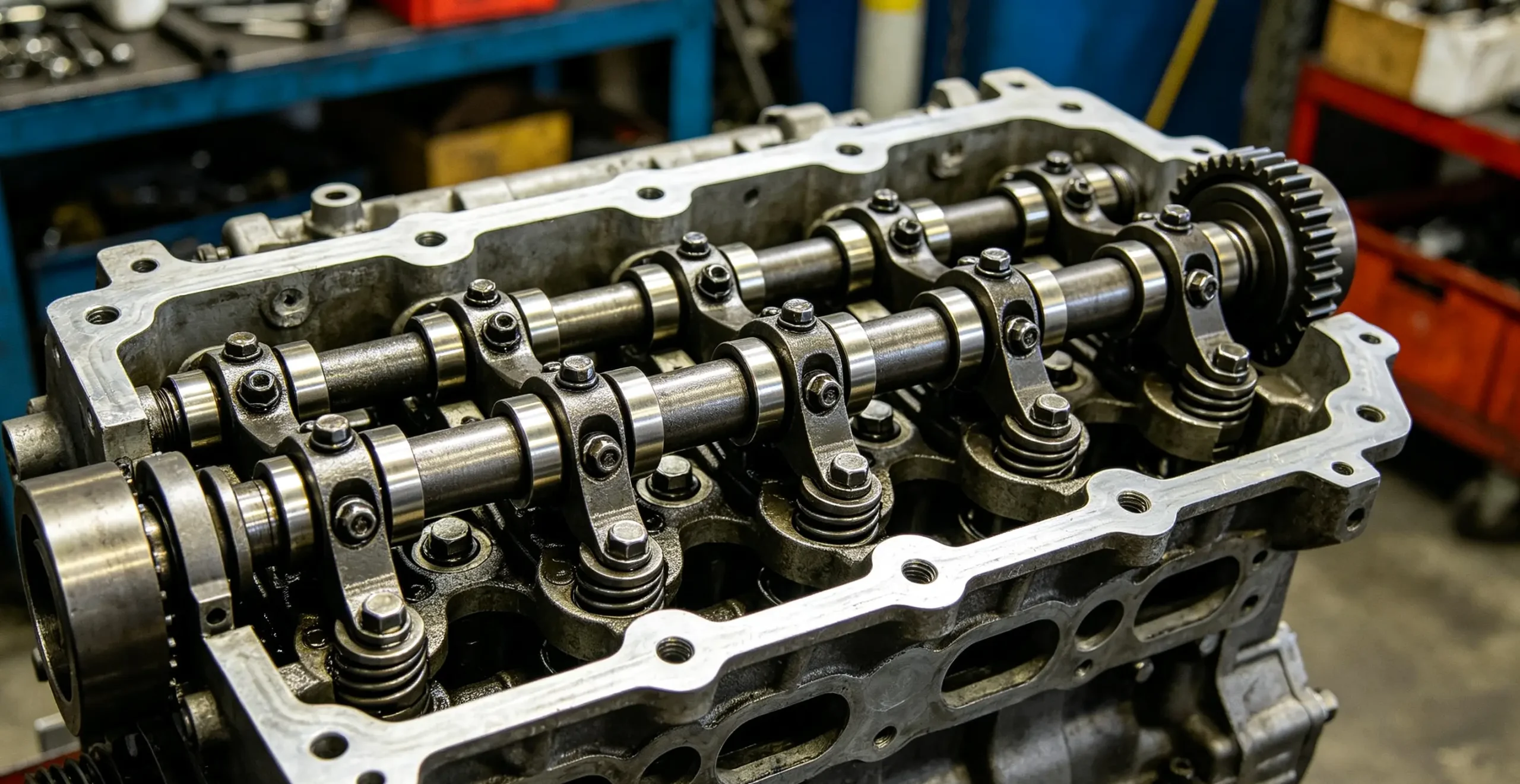
Common Rocker Arm Shaft Issues & Visible Symptoms (Stage-by-Stage Breakdown)
Different from sudden engine electrical faults, rocker arm shaft failures are typical progressive deteriorating mechanical faults, which have obvious stage differentiation in terms of fault manifestation, performance impact, and maintenance difficulty. According to the on-site maintenance fault statistics of heavy-duty truck diesel engines, the failure process of the rocker arm shaft can be accurately divided into three stages: early latent wear stage (no obvious performance impact), mid-term performance abnormality stage (obvious vehicle parameter change), and late destructive failure stage (mechanical damage risk). Each stage corresponds to unique and distinguishable fault symptoms. Professional maintenance personnel and experienced truck drivers can quickly locate shaft faults and judge the failure degree through subtle vehicle operation changes, so as to carry out maintenance and replacement in advance, avoid minor faults evolving into major overhaul accidents, and greatly reduce vehicle maintenance costs and downtime losses. The following is a detailed and refined analysis of five common rocker arm shaft faults and their full-stage symptom characteristics.
1. Shaft Surface Uniform Wear & Journal Scoring (Most Common Fault)
Shaft surface uniform wear and local journal scoring are the highest-incidence rocker arm shaft faults in heavy-duty truck operation, accounting for more than 60% of all shaft-related valve train failures. This fault is mainly caused by long-term abrasive friction between the shaft surface and the rocker arm bushing, as well as oil impurity scratching. After the engine runs for a long time, the tiny metal wear debris, carbon deposits, and dust impurities in the engine oil continuously circulate between the shaft and the bushing with the oil liquid, forming abrasive wear. On the one hand, it causes uniform diameter reduction of the shaft surface; on the other hand, it forms irregular linear scratch grooves and pitted corrosion marks on the local journal surface. After the shaft diameter is reduced and the surface is scratched, the matching gap between the shaft body and the rocker arm bushing far exceeds the factory standard 0.02mm-0.05mm range, resulting in excessive clearance. In the engine working state, the rocker arm can produce obvious radial shaking and up-and-down offset movement when rotating, which makes the valve pressing position deviate, the valve opening stroke unstable, and the valve timing accuracy decreased significantly.
The symptom manifestations of shaft wear and scoring have obvious temperature and speed differentiation characteristics, which are the key basis for accurate fault judgment. In the early latent stage of wear, the most typical manifestation is regular subtle ticking mechanical noise from the cylinder head valve cover during cold start and low-temperature idling. At low temperature, the engine oil has high viscosity and poor fluidity, cannot quickly fill the excessive gap after shaft wear, and the oil film protection is insufficient, resulting in slight metal collision and friction between the rocker arm and the shaft body to form abnormal noise. After the engine water temperature and oil temperature rise to the normal working temperature of 80-90℃, the engine oil fluidity is improved, the oil film fills the gap, and the thermal expansion of metal parts reduces the matching gap, so the abnormal noise will temporarily disappear or weaken significantly. Most drivers misjudge this phenomenon as normal cold start mechanical noise and ignore hidden wear faults. With the continuous accumulation of wear mileage, the shaft gap continues to increase, and the abnormal noise will no longer disappear after heating up, and will become louder synchronously with the increase of engine speed and load.
In addition to abnormal noise, shaft wear and scoring will also bring subtle engine performance changes in the early stage: unstable idle speed, small floating fluctuation of engine tachometer, slight jitter of the vehicle body during no-load idling, delayed accelerator response, and insufficient power reserve during rapid acceleration. In the mid-term failure stage, the excessive gap leads to serious disorder of rocker arm movement, obvious insufficient engine power, slow speed rise during heavy-load climbing, increased fuel consumption per 100 kilometers, and occasional black smoke exhaust. In actual maintenance, many technicians only replace the worn rocker arm bushing and rocker arm assembly after hearing abnormal noise, but the worn and scored shaft body is not replaced. The uneven surface of the old shaft will quickly wear the new bushing again, resulting in the recurrence of abnormal noise within a short time after maintenance, which is the typical characteristic of unresolved shaft wear faults.
2. Rocker Arm Shaft Sticking & Inflexible Rotation
Rocker arm shaft sticking and inflexible rotation are typical lubrication failure faults, which are mainly caused by oil passage blockage, oil deterioration, and shaft surface glue and carbon deposition. After the truck runs for a long time without changing the oil, the engine oil will deteriorate and oxidize to produce a large amount of colloidal oil sludge and carbon deposits. These impurities will adhere to the radial oil outlet holes and axial oil passages of the rocker arm shaft, causing gradual blockage of the lubrication channel. When the oil passage is completely blocked, the lubricating oil cannot be delivered to the matching gap between the shaft body and the rocker arm bushing, resulting in complete loss of oil film protection and long-term dry friction between metals. Dry friction will generate high temperature instantaneously, causing the surface of the shaft body and the inner hole of the bushing to generate high-temperature carbon deposition and metal glue, making the originally flexible rotating rocker arm stuck on the shaft body and unable to rotate freely, forming a semi-locked or fully locked stagnation state.
The performance symptoms of shaft sticking faults are very prominent in the mid-term, and have strong correlation with engine load changes. After the rocker arm is stuck and cannot reset flexibly, the valve reset speed is delayed, the valve cannot be completely closed in place within the factory preset time, resulting in insufficient cylinder sealing, air leakage in the combustion chamber, and incomplete exhaust of exhaust gas. During no-load and light-load operation of the vehicle, the fault symptom is relatively mild, only manifested as slight jitter and increased fuel consumption; during heavy-load climbing, high-speed driving, and full-load acceleration, the engine combustion pressure increases sharply, the incomplete combustion problem is aggravated, and obvious black smoke will be discharged from the exhaust pipe continuously. At the same time, the engine will have intermittent cylinder misfire phenomenon, with irregular exhaust sound and obvious power stalling.
This type of shaft sticking fault is extremely easy to be misdiagnosed as fuel system failure. Many maintenance personnel will repeatedly clean fuel injectors, replace diesel filters, and handle emulsified engine oil problems, but the power failure and black smoke faults still cannot be solved. The fundamental reason is that the hidden mechanical jamming of the rocker arm shaft is not eliminated. In the late stage of sticking failure, the long-term forced operation of the stuck rocker arm will cause excessive local stress on the shaft body, resulting in local fatigue cracking of the shaft body, and even fracture failure in severe cases, directly causing valve train collapse and triggering major engine faults.
3. Bent & Deformed Rocker Arm Shaft
Micro-bending and overall deformation of the rocker arm shaft are hidden mechanical damage faults caused by thermal fatigue and external force impact, which are difficult to find through visual observation and can only be accurately detected through professional straightness detection tools. The rocker arm shaft works in the high-temperature environment of the cylinder head for a long time. When the engine has frequent high-temperature faults such as water temperature overheating and boiling, the shaft body will produce repeated thermal expansion and cold contraction cycles. Long-term thermal cycle impact will cause metal fatigue of the alloy steel material, resulting in irreversible micro-bending deformation of the shaft body. In addition, non-standard maintenance operations such as brute force knocking during disassembly and unbalanced bolt torque during reinstallation will also cause invisible bending and distortion of the shaft body. For trucks that often run on bumpy mountain roads and construction sites, long-term severe vibration impact will also induce slow deformation of the rocker arm shaft.
The most essential hazard of shaft bending deformation is the destruction of the overall synchronization balance of the valve train. The deformed shaft body has inconsistent straightness at each station, resulting in different matching gaps between the shaft body and each group of rocker arms. Some rocker arms have excessive gaps with delayed valve opening, some have too small gaps with unclosed valves, and the valve lift and opening time of each cylinder are completely inconsistent. The direct result is unbalanced combustion of each cylinder of the engine, chaotic combustion rhythm, and overall power disorder.
The typical symptoms of shaft deformation are highly recognizable: unstable engine idle speed, irregular body jitter, obvious difference in operating sound of each cylinder, and frequent water temperature high-temperature alarms after long-time operation. When the deformation degree is mild, the vehicle can run normally but has poor power and high fuel consumption; when the deformation is serious, the engine will have continuous violent jitter, frequent misfire fault codes, and even automatic flameout during idling. Severe shaft bending will cause local stress concentration on the shaft body and single-point overload of the rocker arm, which is very easy to cause early fracture of the rocker arm and valve collision between the valve and piston. This destructive damage mechanism is completely consistent with heavy-duty truck cylinder head failure, which will lead to cylinder head deformation, valve bending, piston top damage, and other major faults, requiring full engine overhaul and bringing extremely high maintenance costs.
4. Loose Shaft Positioning & Axial Play
The rocker arm shaft relies on the combined limit of positioning bolts at both ends and outer snap rings to fix the axial position, ensuring that the shaft body does not shift left and right during operation. After the truck runs for a long time, the continuous high-frequency vibration of the engine will cause the positioning fixing bolts to loosen gradually, and the limit snap rings will produce elastic fatigue and displacement and falling off. Once the limit structure fails, the rocker arm shaft will lose its fixed positioning and produce irregular axial sliding and left-right offset play during engine operation. The offset shaft body will drive all rocker arms to deviate from the standard working track, resulting in chaotic valve lift, disordered valve timing, and completely broken intake and exhaust rhythm.
The fault of shaft positioning looseness and axial play belongs to hidden mechanical deviation, with no obvious damage to parts and normal visual appearance, so it is the most difficult valve train fault to diagnose. Its typical symptom characteristics are sudden and irregular power faults: the engine power is normal during stable driving, but the power drops suddenly and the accelerator response is delayed during acceleration and climbing; the exhaust sound is irregular, with occasional muffled sound and backfire; in severe cases, the engine will stall automatically during idle speed and low-speed driving. Many maintenance personnel repeatedly check the engine oil circuit, gas circuit, and electrical system but find no faults, which is basically caused by hidden shaft axial play.
5. Shaft Oil Hole Blockage & Local Dry Friction Failure
The tiny radial oil holes on the rocker arm shaft are the core channels for independent lubrication of each rocker arm station. Long-term use of inferior engine oil, overdue oil replacement, and failure to replace oil filters in time will lead to a large amount of oil sludge, carbon deposits, and metal impurities accumulated in the engine oil circuit. These fine impurities will gradually deposit and block the tiny oil holes on the shaft body, resulting in the interruption of lubricating oil supply at individual rocker arm positions. The blocked stations lose oil film protection, and continuous dry friction occurs between the shaft body and the rocker arm bushing, while other normal stations are well lubricated. This causes inconsistent wear degree of each station of the same shaft body, local overheating and discoloration of the blocked position, rapid wear and groove scratching, and accelerated aging and damage of local parts.
The symptoms of oil hole blockage are local and progressive: in the early stage, only individual cylinders have slight jitter and unstable power; with the aggravation of blockage and dry friction wear, the local gap increases, the abnormal noise of individual cylinders is obvious, and the fuel consumption rises abnormally. If not cleaned and maintained in time, local dry friction will expand to the entire shaft body, inducing comprehensive wear and jamming faults, and evolving into a major valve train failure.
Root Causes of Truck Rocker Arm Shaft Premature Failure (In-Depth Analysis)
According to the statistical analysis of 1000+ heavy-duty truck engine valve train maintenance cases, the design service life of genuine qualified rocker arm shafts under standard working conditions and standardized maintenance is 200,000-250,000 kilometers. More than 95% of rocker arm shaft premature failures (failure within 100,000 kilometers) are not caused by natural aging and fatigue damage of parts, but are completely derived from human improper use, non-standard maintenance, inferior accessory matching, and working environment impact. Most truck owners only pay attention to the failure phenomenon but ignore the essential inducements of faults, resulting in repeated repair and repeated damage of rocker arm shafts. This chapter deeply sorts out five core root causes of premature shaft failure, combines on-site maintenance practice to analyze the failure mechanism in detail, and provides targeted avoidance schemes for daily vehicle use and maintenance.
1. Inferior Lubricating Oil & Overdue Oil Replacement (Primary Cause)
Lubrication system failure is the number one cause of rocker arm shaft wear, jamming, and deformation, accounting for more than 70% of all shaft failure cases. In order to save short-term operating costs, many individual truck drivers and small fleets choose low-cost inferior fake engine oil and unqualified auxiliary oil products. This kind of inferior engine oil has serious quality defects: low high-temperature oxidation stability, easy thinning and deterioration under engine high-temperature working environment, inability to maintain stable viscosity, and lack of anti-wear, anti-oxidation, and anti-carbon additives required for engine operation. After use, it cannot form a dense and wear-resistant protective oil film on the surface of the rocker arm shaft and bushing, resulting in direct metal dry friction and rapid abrasive wear of precision parts. At the same time, inferior engine oil contains a large number of mechanical impurities and residual impurities, which will continuously scratch the shaft journal surface, form irregular scratches, and accelerate shaft damage.
Overdue oil replacement and irregular filter element replacement are also important lubrication failure inducements. Many truck owners extend the oil replacement cycle indefinitely based on driving experience. The engine oil that has exceeded the service life has completely failed in lubrication, heat dissipation, and anti-wear performance, and accumulates a large amount of metal wear debris, carbon deposits, and oil sludge. These impurities circulate in the engine oil circuit for a long time, block the rocker arm shaft oil holes and cylinder head lubrication channels, cause local lubrication interruption, and induce shaft jamming and local dry friction failure. Even if the vehicle is equipped with a genuine rocker arm shaft, long-term use of unqualified lubricating oil and overdue oil replacement will inevitably lead to premature scrapping of the shaft body.
2. Long-Term Engine High-Temperature Operation & Thermal Fatigue Deformation
The cooling system is the key to maintaining the constant temperature working environment of the engine cylinder head and protecting the rocker arm shaft. When the truck has cooling system faults such as radiator dust blockage, water scale accumulation, thermostat failure, insufficient coolant, and water pump power attenuation, the engine cannot dissipate heat normally, resulting in long-term high-temperature operation of the cylinder head. The rocker arm shaft located in the high-temperature inner cavity of the cylinder head will bear continuous high-temperature baking, resulting in repeated thermal expansion and cold contraction of the alloy steel material. Long-term thermal cycle impact will cause metal fatigue of the shaft body, reduce structural toughness and stability, and produce irreversible micro-bending deformation and torsion distortion.
In addition, frequent high-temperature operation will also accelerate the aging and deterioration of engine oil, reduce lubrication performance, form high-temperature carbon deposits on the shaft surface, block oil holes, and form a vicious cycle of “high temperature – poor lubrication – shaft damage – more serious high temperature”. Trucks that often work in high-temperature environments such as summer highway transportation, open-pit mines, and construction sites have a significantly higher probability of rocker arm shaft thermal deformation failure than ordinary working condition vehicles.
3. Non-Standard Disassembly & Irregular Maintenance Operation
Rocker arm shaft disassembly and installation belong to high-precision engine mechanical maintenance operations, which have strict requirements on operation tools, operation steps, bolt torque, and part sequencing. However, most grassroots maintenance shops adopt rough and non-standard operation modes in actual maintenance. In the disassembly process, maintenance personnel often use iron tools to knock the shaft body and rocker arm hard to disassemble stuck parts. Instant external force impact will cause invisible micro-deformation and internal metal damage to the high-precision shaft body, which cannot be observed by the naked eye, but will gradually amplify during engine operation, leading to early failure.
In the reinstallation process, non-standard operation problems are more prominent: asymmetric bolt tightening torque, random placement of rocker arm installation sequence, wrong alignment of shaft oil holes, and omitted limit snap ring installation. These irregular operations will lead to unbalanced stress on the shaft body, deviated working track, blocked lubrication channels, and loose positioning clearance. Many newly replaced rocker arm shafts fail in a short time after maintenance, which is basically caused by non-standard installation and debugging, not part quality problems.
4. Inferior Imitation & Refurbished Accessories Matching Failure
The market is flooded with a large number of low-cost inferior imitation rocker arm shafts and second-hand refurbished shafts. These unqualified accessories have serious defects in material selection, processing technology, heat treatment, and tolerance accuracy. Inferior shafts adopt ordinary carbon steel instead of high-strength alloy steel, with low surface hardness, poor wear resistance, and easy deformation under high temperature and impact load. The processing precision is low, the shaft surface roughness is unqualified, and the matching tolerance with the rocker arm bushing exceeds the factory standard, resulting in excessive clearance or jamming after installation. Second-hand refurbished shafts are recycled old shafts after simple polishing and cleaning, with hidden fatigue damage and internal micro-cracks inside the shaft body, which are very easy to break and fail after installation.
Matching unqualified rocker arm shafts and supporting accessories will not only fail to solve the original valve train faults, but also induce more serious secondary failures such as rocker arm wear acceleration, valve timing disorder, and cylinder combustion imbalance. In order to avoid accessory matching risks, it is recommended that fleet maintenance and individual car owners cooperate with professional and formal Sinotruk spare parts suppliers to purchase fully compatible genuine supporting parts, so as to ensure maintenance quality and long-term stable operation of the engine.
5. Long-Term Overload & Harsh Driving Habits
In order to pursue transportation economic benefits, most heavy-duty trucks are in long-term overload and over-speed operation for a long time. Vehicle overload will sharply increase the engine’s combustion pressure and output torque, making the rocker arm shaft bear far higher impact load and pressure than the factory design standard. Long-term overload impact will cause continuous metal fatigue of the shaft body, accelerate surface wear and gap expansion, and greatly shorten the service life of the shaft. Frequent harsh driving behaviors such as rapid acceleration, sudden deceleration, slope rushing, and high-speed gear dragging will generate instantaneous sharp load changes on the valve train system, forming periodic impact force on the rocker arm shaft, aggravating fatigue damage and deformation.
In addition, long-term idle parking and idle operation are also easily overlooked failure inducements. When the engine is idling, the oil pump pressure decreases, the engine oil circulation speed slows down, the lubrication volume of the cylinder head valve train area is insufficient, the oil film thickness decreases, and the rocker arm shaft is in a state of insufficient lubrication for a long time, resulting in hidden abrasive wear, which gradually accumulates into obvious faults.
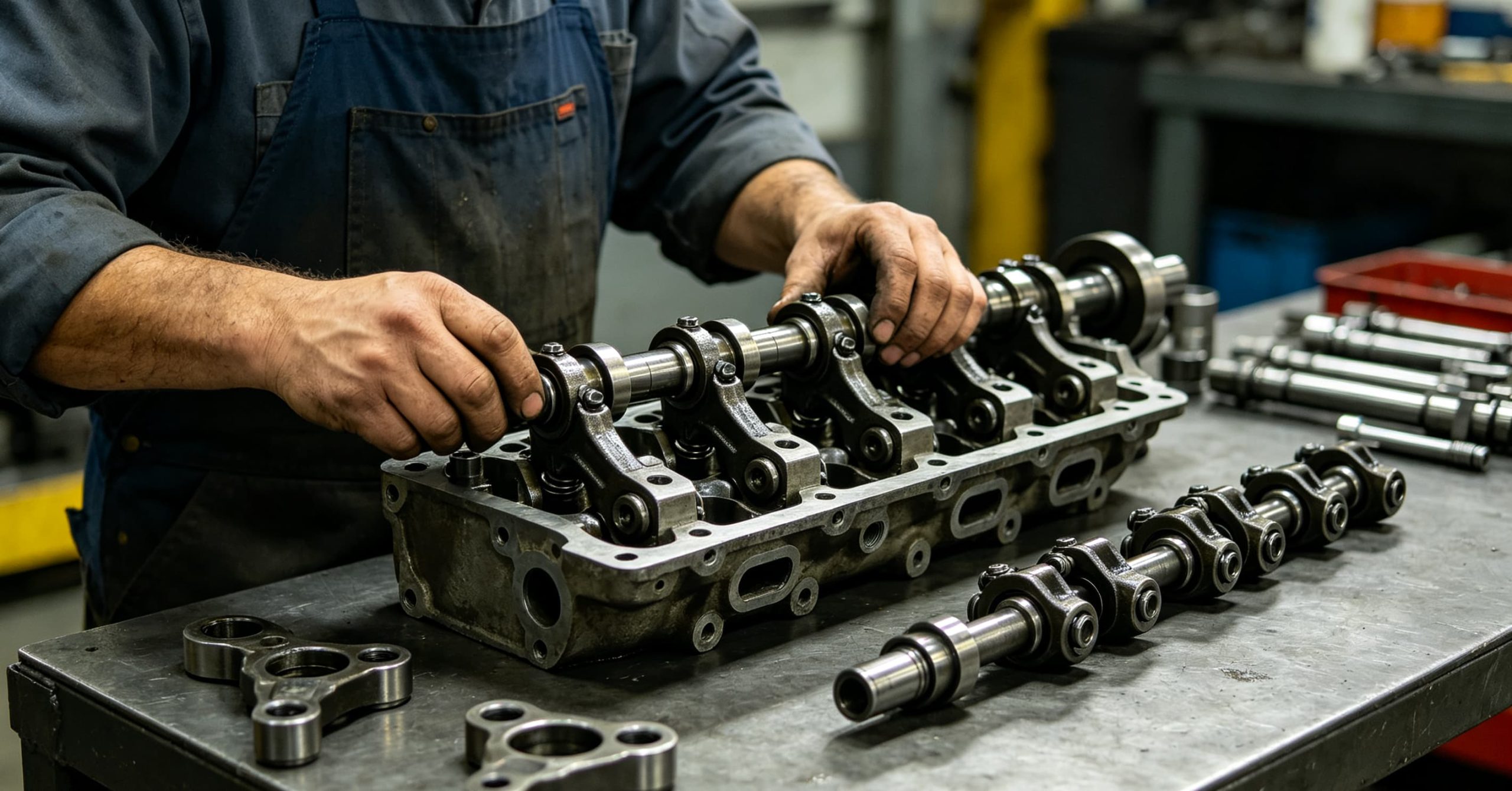
Step-by-Step Professional Guide to Fix Truck Rocker Arm Shaft Issues
Fixing heavy-duty truck rocker arm shaft faults cannot rely on simple part replacement and blind debugging. It must follow a complete set of standardized processes of “preparation – disassembly – comprehensive inspection – deep cleaning – precision installation – parameter debugging – test verification”, eliminate all hidden faults one by one, and avoid incomplete maintenance leading to repeated failures. The following is a full-process refined professional repair process summarized based on a large number of on-site maintenance cases, which is suitable for all mainstream heavy-duty diesel truck models, with strong operability and practicability.
Step 1: Engine Shutdown & Standard Pre-Repair Preparation
First, turn off the engine completely and park the vehicle on a horizontal ground to ensure the engine is in a static and balanced state. It is strictly forbidden to disassemble and maintain the engine when it is hot and running. Wait for more than 2 hours after shutdown to completely cool the cylinder head and engine body, eliminate the error of part gap measurement caused by thermal expansion of metal parts, and ensure the accuracy of subsequent inspection and debugging data. Disconnect the vehicle battery negative terminal to avoid short circuit and electrical system fault alarm during maintenance.
Prepare professional maintenance tools and auxiliary materials in advance: high-precision torque wrench, feeler gauge, straight ruler, level gauge, special valve train disassembly tool, compressed air gun, professional engine carbon cleaning agent, clean cotton cloth, and new sealing gaskets. Check the tool accuracy to ensure that the measuring tool data is accurate, laying a foundation for standardized maintenance.
Step 2: Remove Valve Cover & Clean Surface Dust and Oil Sludge
Loosen the valve cover fixing bolts in diagonal symmetrical order to avoid cylinder head deformation caused by one-side force. After all bolts are loosened, gently lift the valve cover to avoid scratching the sealing surface. Remove the old valve cover gasket and completely clean the aging colloid, oil sludge, and dust on the gasket surface and cylinder head surface to ensure a clean and flat installation base surface. Observe the overall working state of the internal rocker arm assembly, record the position of abnormal wear, oil leakage, and carbon deposition, initially judge the fault scope, and make targeted marks for subsequent disassembly and inspection.
Step 3: Sequential Dismantling of Rocker Arms & Integral Shaft Removal
First, remove the limit snap rings and positioning fixing bolts at both ends of the rocker arm shaft with special tools, and place the disassembled bolts and snap rings in classified storage to avoid loss and mixing. Number and mark each group of rocker arms in the order of installation from left to right to ensure the original position reinstallation, avoid installation dislocation and gap disorder caused by disordered placement. Take out each group of rocker arms and springs in turn, check the wear state of rollers and spring elasticity preliminarily, and replace severely worn and fatigued parts in time. After all rocker arms are removed, slowly and horizontally pull out the integral rocker arm shaft to avoid shaking and tilting, prevent secondary scratch damage to the polished surface of the shaft body caused by inclined pulling, and protect the shaft precision to the greatest extent.
Step 4: Comprehensive Precision Inspection & Fault Final Confirmation
Wipe the disassembled rocker arm shaft repeatedly with a clean dust-free cotton cloth to completely remove surface oil sludge and carbon deposits, so that the shaft surface is clean and free of impurities for comprehensive inspection. First, visually observe the surface state: check whether there are uniform wear marks, irregular scratch grooves, pitted corrosion, and high-temperature discoloration on the shaft journal surface. Second, use a professional straight ruler and feeler gauge to detect the straightness of the shaft body to judge whether there is micro-bending and torsion deformation. Third, use compressed air to blow through all axial and radial oil holes to check whether the oil passages are completely unobstructed and confirm whether there is blockage. Fourth, check the wear degree of the limit clamping grooves and positioning pin holes at both ends to judge whether the positioning failure is caused by hole expansion and wear.
After comprehensive inspection, any of the following situations requires direct replacement of the rocker arm shaft: surface wear exceeds 0.03mm, obvious scratch grooves and corrosion marks exist, shaft straightness deformation exceeds 0.02mm, oil holes are completely blocked and cannot be cleaned, and positioning holes are worn and expanded. It is strictly forbidden to continue to use repaired and polished old shafts, so as to avoid hidden faults.
Step 5: Deep Cleaning of Oil Passages & Full Part Decontamination
For reusable qualified shafts and disassembled rocker arm parts, carry out deep decontamination and cleaning. Spray professional engine carbon cleaning agent on the shaft surface and oil holes, soak for 10-15 minutes to fully dissolve stubborn carbon deposits and colloidal oil sludge, and then use high-pressure compressed air to repeatedly blow through the axial and radial oil passages until the oil passages are completely unobstructed and no impurities are discharged. Clean the inner holes of the rocker arm bushing, spring gaps, valve stem surfaces, and cylinder head lubrication oil passages one by one to completely remove all residual metal debris and carbon deposits, ensure the smooth circulation of the entire lubrication system, and eliminate hidden dangers of abrasive wear.
Step 6: Precision Installation of New Shaft & Synchronous Accessory Replacement
Take the new genuine rocker arm shaft, check the surface precision and oil hole position again, and confirm that the parts are complete and qualified. Horizontally install the new shaft into the cylinder head installation position, accurately align the oil hole direction and positioning hole position, ensure that the shaft body is flat and not offset, and the stress is uniform. Install limit snap rings and positioning bolts in place, and tighten the bolts according to the factory standard torque to avoid loose positioning and excessive compression. Reinstall the marked rocker arms, springs, and gaskets in the original sequence to ensure that each rocker arm rotates flexibly and smoothly without jamming and stagnation. Synchronously replace all aging gaskets, fatigued springs, and worn bushings to avoid secondary faults caused by aging of supporting parts.
Step 7: Standard Valve Clearance Calibration & Precision Debugging
Rocker arm shaft replacement will change the original matching gap of the valve train, so valve clearance recalibration is a necessary core step after maintenance, which directly determines the engine operating state. Strictly refer to the engine factory parameter standard, use a high-precision feeler gauge to detect the intake valve clearance and exhaust valve clearance of each cylinder one by one, fine-tune the rocker arm adjusting bolts, and control the clearance within the factory standard range. After debugging, repeatedly detect and confirm to ensure that the clearance of all cylinders is consistent and there is no deviation, avoid power jitter and abnormal noise caused by uneven valve clearance.
Step 8: Idle Operation Test & Load Road Test Verification
After the installation and debugging are completed, clean the installation site, install the new valve cover gasket and fix the valve cover, and tighten the bolts diagonally according to the standard torque. Start the engine, run at idle speed for 15-20 minutes, observe the engine operating state in real time: check whether there is abnormal mechanical noise in the cylinder head, whether the idle speed is stable, whether the exhaust gas is normal, and whether there is oil leakage at the valve cover. After the idle test is qualified, carry out no-load and half-load road tests, accelerate smoothly, climb and decelerate to verify the accelerator sensitivity, power stability, and exhaust state. After confirming that all faults are completely eliminated and the engine operates normally, the maintenance is completed.
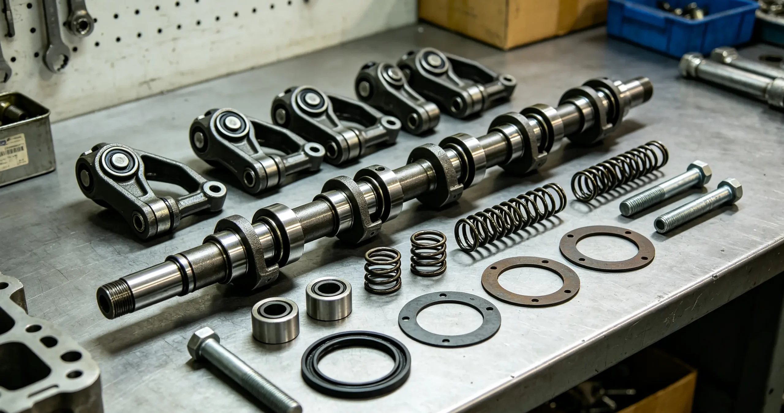
Long-Term Maintenance & Scientific Fault Prevention Strategies
More than 90% of rocker arm shaft failures are preventable through standardized daily maintenance and scientific vehicle use habits. Formulating targeted long-term maintenance plans can effectively extend the service life of the rocker arm shaft and the entire valve train system, eliminate early hidden faults, and reduce vehicle operating and maintenance costs. The following systematic prevention strategies are summarized for heavy-duty truck long-term operation scenarios, suitable for all working conditions and models.
First, strictly control lubrication quality and standardize oil replacement cycle. Always use brand-qualified engine oil and genuine filter elements that meet the engine factory standards, and completely abandon inferior lubricating oil and fake filter elements. Formulate differentiated replacement cycles according to working conditions: 50,000 kilometers for standard highway logistics transportation; shorten the cycle to 30,000-40,000 kilometers for harsh working conditions such as mining areas, construction sites, and mountain road operations to ensure clean oil circuits and stable lubrication performance, and avoid abrasive wear and oil passage blockage.
Second, standardize driving habits and reduce engine load impact. Strictly abide by the vehicle rated load standard, refuse long-term overload and over-speed driving, reduce frequent rapid acceleration, emergency braking, and slope rushing operations, and avoid instantaneous sharp load impact on the valve train system. Reduce long-term idle parking time, turn off the engine in time when waiting for loading and unloading, avoid low oil pressure and insufficient lubrication during idling, and reduce hidden wear of the rocker arm shaft.
Third, establish daily valve train fault inspection mechanism. Take cold start abnormal noise, idle jitter, exhaust smoke state, and accelerator response speed as daily key inspection items. Carefully observe the engine operating state every cold start, record subtle abnormal changes, and arrange professional disassembly and inspection in time once hidden faults are found, so as to avoid minor faults deteriorating into destructive major failures.
Fourth, maintain the stability of the engine cooling system. Regularly clean radiator dust and water scale, check coolant capacity and cleanliness, replace aging thermostats, water pipes, and water pump accessories regularly, eliminate engine high-temperature hidden dangers, avoid thermal deformation and fatigue damage of the rocker arm shaft caused by long-term high-temperature operation, and maintain a constant temperature working environment for the valve train system.
Fifth, choose professional standardized maintenance teams. All valve train disassembly, replacement, and debugging operations must be completed by professional technicians with special tools and standard processes. Refuse rough maintenance and non-standard debugging, ensure accurate installation position, uniform bolt torque, and standard valve clearance, and avoid artificial secondary damage to the rocker arm shaft.
FAQ About Truck Rocker Arm Shaft Problems (Detailed Answers)
Q1: Can a slightly worn rocker arm shaft continue to be used temporarily? Absolutely not recommended. Although slight shaft wear will not cause obvious power faults and abnormal noise in a short time, the worn shaft surface has lost the factory hardening protection layer, and the matching gap has exceeded the standard. Under the high-frequency reciprocating operation of the engine, the wear degree will expand exponentially in a short time, rapidly inducing rocker arm shaking, valve timing disorder, and abnormal noise. Continuing to use it will eventually lead to shaft jamming, valve collision, and cylinder misfire, bringing higher overhaul costs. For the sake of long-term vehicle stability, it must be replaced directly once wear is found.
Q2: Why does the cylinder head ticking noise still exist after replacing new rocker arms? This is a very common maintenance misjudgment problem. Most maintenance personnel only replace the wearable rocker arm and bushing, but ignore the worn, scored, or deformed rocker arm shaft. The old shaft with excessive wear and uneven surface will quickly wear the new rocker arm bushing, resulting in unchanged abnormal noise and repeated faults. The fundamental solution is to disassemble and inspect the rocker arm shaft synchronously during rocker arm replacement, and replace the shaft together if hidden damage is found.
Q3: Is it necessary to replace the rocker arm shaft and rocker arms as a complete set? Yes, complete set replacement is the most scientific maintenance method. The rocker arm shaft and the rocker arm bushing are mutually worn matching parts, which form a matching fit gap after long-term operation. If only a single part is replaced, the new and old parts cannot form a standard matching gap, resulting in poor rotation flexibility, accelerated new part wear, and secondary faults. Complete set of genuine parts replacement can ensure the coordination precision of the valve train system and long-term stable operation.
Q4: What is the standard service life of a genuine truck rocker arm shaft? Under standard lubrication conditions, normal load operation, and standardized daily maintenance, the service life of genuine factory rocker arm shafts can reach 200,000-250,000 kilometers. For vehicles operating in harsh environments such as frequent overload, high temperature, and dust, and vehicles with irregular oil replacement, the service life will be shortened to 120,000-150,000 kilometers, and early inspection and replacement are recommended.
Q5: How to quickly distinguish rocker arm shaft faults from ordinary rocker arm faults? The core distinguishing feature is the fault recurrence and temperature change law. Ordinary rocker arm wear noise will disappear completely after replacing the rocker arm; while shaft fault noise will recur after replacing the rocker arm, and has obvious cold start loud noise and hot car weakening characteristics. In addition, shaft faults are often accompanied by unstable idle speed and increased fuel consumption, while single rocker arm wear only has abnormal noise without obvious power attenuation.
Q6: Will blocked shaft oil holes cause engine overhaul? Long-term untreated oil hole blockage will lead to local dry friction and severe wear of the shaft body, resulting in shaft jamming and deformation, disordered valve timing, and valve collision with the piston in severe cases, causing irreversible damage to valves, pistons, and cylinder heads, which ultimately requires full engine overhaul. Timely cleaning of oil holes and maintenance can completely avoid major overhaul accidents.
Conclusion
The rocker arm shaft is the precision support core and positioning foundation of the heavy-duty truck diesel engine valve train system, and its operating stability and structural integrity directly determine the valve timing accuracy, cylinder combustion balance, power output efficiency, and long-term operation safety of the entire engine. Different from easily consumable valve train parts, rocker arm shaft faults are hidden and progressive, which are extremely easy to be ignored and misdiagnosed in daily maintenance. A large number of practical maintenance cases prove that most recurrent cylinder head abnormal noise, unstable idle speed, increased fuel consumption, power attenuation, and intermittent cylinder misfire faults are not caused by conventional wearable parts, but are rooted in hidden damage such as rocker arm shaft wear, scoring, bending deformation, and oil passage blockage.
For fleet managers and individual truck drivers, establishing a scientific valve train full-part maintenance awareness is crucial to reducing vehicle failure rates, controlling operating costs, and improving transportation efficiency. Abandoning the one-sided maintenance concept of only replacing wearable parts, standardizing daily lubrication and oil replacement habits, regularly inspecting hidden faults of the rocker arm shaft, and adopting standardized disassembly inspection and genuine full-set parts replacement methods can completely eliminate all shaft-related engine faults. For users who need genuine heavy-duty truck engine valve train accessories, professional fault diagnosis, and standardized repair guidance, you can visit Mettlead to obtain one-stop matching solutions and technical support, fully protect the stable and efficient operation of logistics transport vehicles, and reduce repeated maintenance and downtime losses.


