
How to Check a Crankshaft Position Sensor: A Pro Guide
Why the Crank Position Sensor Matters to Engine Reliability
The crankshaft sits at the mechanical heart of every internal combustion engine, converting reciprocating piston motion into the rotational force that drives the wheels. Monitoring that rotation is a small but critical electronic component: the position sensor. When this device fails, the engine control unit (ECU) loses its primary timing reference, and performance degrades fast.
For technicians and fleet engineers, diagnosing this sensor accurately saves both downtime and unnecessary parts swaps. This guide walks through verified test procedures, signal expectations, and longevity practices grounded in real workshop data. Our goal is to help you isolate the true fault on the first attempt, so you keep vehicles moving and customers satisfied.
Think of the crank signal as the engine's heartbeat monitor. Without a steady pulse, the ECU is effectively driving blind, unsure when to fire each spark or open each injector. Understanding why that signal matters frames every diagnostic decision that follows, and it explains why a part that costs little can stop a vehicle worth far more from starting at all.
There is also a wider reliability story at play. A timing pickup that drifts out of specification rarely fails in isolation; it usually signals stress somewhere in the surrounding system, whether that is heat soak from a nearby exhaust component, a weeping seal, or a harness that has rubbed thin over years of vibration. Treating the sensor as a window into engine health, rather than a disposable part, changes how you approach the whole job. The technicians who consistently fix a no-start on the first visit are the ones who read the signal as a symptom of system condition, not just a binary pass or fail.
How Does a Crankshaft Work and Where Does the Sensor Fit?
To appreciate the sensor's job, it helps to understand how does a crankshaft work within the powertrain. The main shaft rotates on bearing journals while connecting rods transfer combustion pressure from each piston, producing a smooth output torque curve.
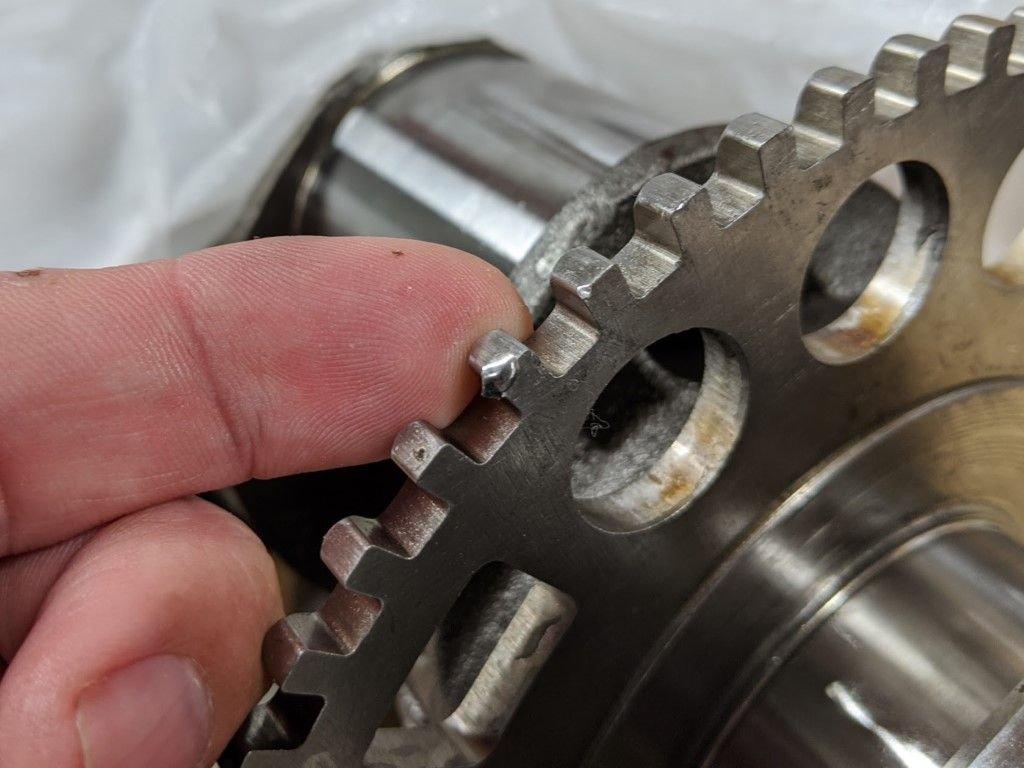
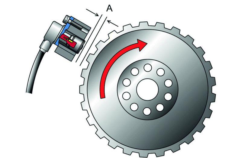
The timing sensor reads a toothed reluctor or trigger wheel mounted on this rotating member. Each passing tooth generates a pulse, telling the ECU exactly where each cylinder is in its cycle. That data governs ignition timing and fuel injection sequencing with millisecond precision.
Most trigger wheels use a deliberate gap, often described as a missing tooth, to mark a reference point. As the wheel spins, the steady stream of pulses pauses briefly at that gap, giving the ECU a fixed landmark it can anchor calculations to. From there, the controller counts teeth to predict where the pistons will be microseconds into the future, allowing it to schedule spark and fuel events ahead of time rather than reacting to them. This predictive loop is why a clean, consistent signal is non-negotiable for smooth running.
A small air gap separates the sensor tip from the trigger wheel, usually less than a millimetre. If debris, a loose mount, or a bent bracket changes that gap, the pulse strength drops and the ECU may misread or lose the signal entirely. Keeping this relationship in mind helps explain many intermittent faults that resist a simple resistance check.
It is worth pausing on the physics, because it shapes everything you will measure later. An inductive pickup works by magnetic induction: as a ferrous tooth sweeps past the magnet inside the sensor, it disturbs the magnetic field and induces a small alternating voltage in the coil. Faster rotation means a stronger, higher-frequency signal, which is exactly why a slow crank from a weak battery can mute the output and mimic a failed part. A Hall-effect unit, by contrast, carries its own power supply and switches a transistor on and off as the teeth pass, delivering a crisp square wave whose amplitude stays stable regardless of speed. Knowing which type you are facing tells you what a healthy reading should look like before you ever connect a probe.
Crankshaft vs Camshaft Difference: Two Sensors, Two Roles
Many technicians conflate the two timing sensors, so clarifying the crankshaft vs camshaft difference prevents misdiagnosis. The lower shaft turns at engine speed and drives the entire assembly, while the camshaft rotates at half that speed to open and close the valves.
The crank sensor establishes the master timing reference; the cam sensor identifies cylinder identification for sequential injection. Confusing one fault code for the other leads to replacing the wrong part, a common and costly error in busy shops.
| Attribute | Crank Position Sensor | Cam Position Sensor |
|---|---|---|
| Rotation speed reference | Engine RPM (1:1) | Half engine RPM (1:2) |
| Primary function | Ignition & injection timing base | Cylinder identification |
| Typical fault code | P0335–P0339 | P0340–P0349 |
| Effect of failure | No-start or stalling | Hard start, rough idle |
A practical way to remember the relationship: the crank pickup tells the ECU how fast and where the engine is turning, while the cam pickup tells it which cylinder is on its compression stroke. On many modern engines the two work as a correlation pair, and the ECU will set a P0016 or related code when their relative positions drift apart. That correlation code often points to mechanical timing problems rather than a failed sensor, which is exactly why understanding both roles up front saves wasted parts.
The distinction also affects how an engine behaves when one fails. Lose the lower-shaft signal and the engine typically will not start at all, because the controller has no master reference to schedule any event. Lose the cam signal on a running engine and many controllers limp along by inferring cylinder identification from the crank data, accepting a hard start or rough idle in exchange for keeping the vehicle mobile. Recognizing which symptom pattern you are seeing narrows the search before you pick up a single tool.
Common Causes of Failure
Replacing a sensor without understanding why it failed often leads to a repeat visit. In our experience supporting workshop teams, the underlying causes cluster into a few predictable categories, and addressing the root cause protects the new part.
| Root Cause | How It Develops | Preventive Action |
|---|---|---|
| Heat fatigue | Repeated thermal cycling near the block cracks internal windings or solder joints | Use heat-rated replacement parts and route harnesses away from exhaust |
| Oil or coolant contamination | A leaking seal coats the sensor tip, weakening the magnetic signal | Repair the leak and clean the mounting bore before reinstalling |
| Vibration and mounting fatigue | Loose bolts widen the air gap and stress the connector | Torque to spec and inspect brackets for cracks |
| Damaged wiring or corrosion | Chafed insulation or green corrosion raises resistance | Repair harness, seal connectors, apply dielectric grease |
| Trigger wheel damage | A chipped or rusted reluctor tooth distorts the pulse | Inspect the wheel during sensor service |
Notice how several causes point back to something other than the pickup itself. A coolant leak that fouls the tip will ruin a brand-new part in weeks, and a widened air gap from a loose bracket will mimic an electrical fault. Solving the customer's actual problem means inspecting the surrounding system, not just swapping the obvious component.
Heat fatigue deserves a closer look because it is the most misleading of the group. A unit mounted low against a hot block endures thousands of expansion and contraction cycles, and over time a hairline crack opens in a solder joint or coil winding. When cold, the metal contracts and the connection closes, so the part tests perfectly on the bench. When the engine reaches operating temperature, the crack widens and the circuit opens, the engine stalls, and the complaint disappears again once everything cools. This is why a single cold resistance reading can send you chasing the wrong lead, and why temperature-aware testing later in this guide matters so much.
Contamination is the second great deceiver. Oil mist from a leaking front main seal or rear timing cover gradually coats the tip with a film that dampens the magnetic field. The signal weakens rather than disappearing outright, so the engine runs ragged or stumbles under load without ever throwing a clean no-start. Before condemning the electronics, pull the unit and inspect the tip; a glaze of baked oil tells you the real fault lives in a seal, not the sensor.
Wiring and connector problems round out the list and are often the easiest to overlook. Years of engine bay heat embrittle insulation, road salt creeps into a poorly sealed connector, and the resulting resistance starves the signal circuit. A careful visual inspection with a gentle tug test on each pin frequently finds the fault faster than any meter, and it costs nothing but a few minutes of attention.
Pro Testing Methods Method 1: OBD Scan Tool (Fastest Check)
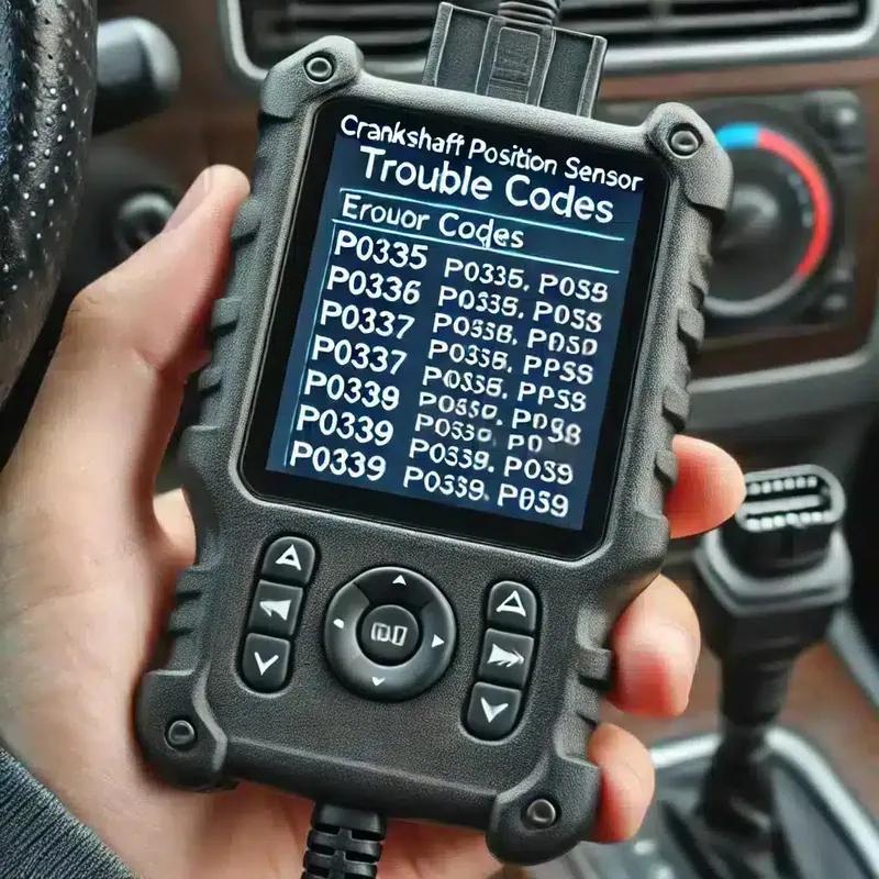
The quickest way to point a finger at the timing circuit is to let the vehicle tell you what it sees. Connect a capable bidirectional scan tool, pull stored and pending diagnostic trouble codes, and note the freeze-frame data that records the conditions present when the fault stored. Codes in the P0335 to P0339 range point straight at the crank signal circuit, while a P0016 correlation code hints at mechanical timing rather than a failed pickup.
Codes alone rarely close a case, though, so move to live data. Monitor the RPM parameter during cranking. A healthy unit produces a stable, rising RPM value the moment the starter engages. A flat-lining zero or a jittery, jumping reading while cranking points directly to signal loss, even when no code has stored yet. This single observation often separates a true timing fault from a fuel or ignition complaint in under a minute, which is why it earns its place as the fastest check.
For intermittent complaints, take the data logging further. Record a live snapshot during a road test or while the engine is hot, then review the trace for momentary RPM dropouts that coincide with the stall. Capturing the fault as it happens is far more conclusive than a stored code, and it often reveals heat-related dropout that a static test in the bay would never reproduce. Many scan tools let you set a trigger so the log freezes automatically the instant RPM falls to zero, which is invaluable when the customer reports a stall that lasts only a heartbeat.
Treat the scan tool as your triage station rather than the final word. It tells you where to look and whether the controller is receiving a usable signal, but it cannot show you the shape or quality of that signal. Use it to confirm the complaint is timing-related, then move to a direct electrical measurement to prove the fault and identify the failed component.
Pro Testing Methods Method 2: Resistance Test (Multimeter)
Once the scan data points at the timing circuit, a digital multimeter confirms whether the pickup itself is the culprit. For inductive (two- or three-wire magnetic) units, unplug the connector and measure resistance across the signal terminals. Most read between 200 and 2,000 ohms; an open reading or a dead short to zero confirms a failed winding. Always compare your measurement against the factory specification for the exact platform, because the healthy range varies more between engines than many technicians expect.
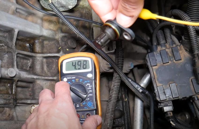
Resistance is only half the picture for magnetic units. With the connector still unplugged, switch the meter to AC volts and crank the engine while back-probing the signal pins. A working inductive pickup generates roughly 0.5 to 2.0 volts AC as the trigger wheel sweeps past. No output during cranking, despite an in-range resistance reading, points to a collapsed magnetic field or a fouled tip rather than a broken coil.
Hall-effect sensors call for a different approach because they are powered devices, not passive coils. Resistance testing tells you nothing useful here. Instead, with the key on, verify the 5-volt or 12-volt reference supply and a clean ground at the connector. Then confirm the supply voltage holds steady under cranking load, not just with the key on, since a sagging reference can starve the sensor at precisely the moment it is needed most.
When resistance falls within range but the complaint persists, repeat the test with the engine at full operating temperature. Heat can open a winding that reads perfectly when cold, and a side-by-side comparison of hot versus cold resistance frequently exposes the heat-fatigue failures described earlier. A clip-on thermocouple and a few minutes of patience often reveal what a single cold reading hides.
| Sensor Type | Test Method | Expected Reading | Failure Indicator |
|---|---|---|---|
| Inductive (magnetic) | Multimeter resistance | 200–2,000 Ω | Open / 0 Ω short |
| Inductive (magnetic) | AC voltage while cranking | 0.5–2.0 V AC | No voltage output |
| Hall-effect | Reference voltage (key on) | 5 V or 12 V supply | Missing supply/ground |
| Any type | Oscilloscope waveform | Clean periodic signal | Dropouts, flat trace |
For the most stubborn intermittent cases, an oscilloscope remains the gold standard and complements the meter work above. Back-probe the signal wire and crank the engine to capture the waveform. A magnetic unit should show a clean AC sine pattern that grows with speed, while a Hall sensor produces a crisp square wave with a missing-tooth synchronization gap. Watch the consistency of the pattern, not just its presence: amplitude that collapses as the engine warms, ragged edges, or a gap that wanders all signal trouble even when the multimeter reads normal. The waveform also confirms the trigger wheel is intact, because a damaged tooth shows up as a distorted pulse in an otherwise even train.
If you need calibrated tooling or sensor specifications for a specific platform, our technical support team maintains documented test values across major engine families, so you can match expected readings to the engine in front of you.
Symptoms of a Bad Crankshaft Position Sensor
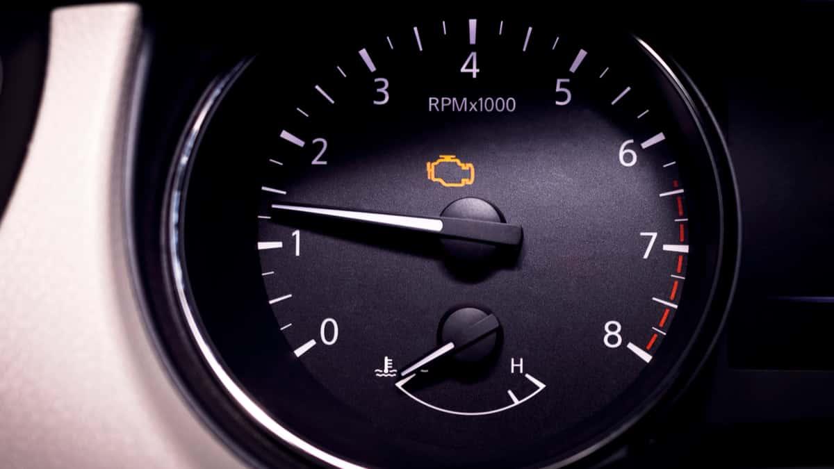
Early detection depends on reading the warning signs correctly. The most reliable failure symptoms include intermittent stalling, extended cranking before start, erratic tachometer behavior, and an illuminated check-engine light with timing-related codes.
Field data from a 2024 commercial-fleet maintenance review indicated that roughly 18% of intermittent no-start complaints traced back to a degrading crank signal rather than fuel or battery faults. Heat-related dropout is especially common: the engine runs until hot, then stalls and refuses to restart until cooled.
Drivers often describe the experience before the codes ever appear, so it pays to listen carefully to the complaint. Watch for these patterns:
- Random stalling at idle or while cruising, often followed by an immediate restart once the engine cools slightly.
- Hesitation or surging under load, as the ECU briefly loses its timing landmark and defaults to a conservative map.
- Hard or extended starting, where the engine cranks several extra seconds before catching.
- A tachometer needle that drops to zero or jumps erratically during the stall, a telltale sign the pulse train has disappeared.
- Reduced fuel economy and a rough idle, because incorrect timing forces the engine to work harder for the same output.
- Intermittent loss of spark or injector pulse, which can leave the engine cranking normally yet refusing to fire until the signal returns.
The pattern of the symptom often reveals the underlying cause. A complaint that appears only after twenty minutes of driving in summer traffic strongly suggests heat fatigue, while a stumble that worsens over rough roads hints at a vibration or connector issue. A driver who reports a gradual decline in starting reliability over months is more likely describing a contaminated tip than a sudden electrical break. Logging these details before you touch the vehicle turns a vague description into a focused test plan.
Because these symptoms overlap with fuel-delivery and ignition problems, treat them as clues rather than proof. The structured tests in this guide turn those clues into a confirmed diagnosis, which is the difference between a confident repair and an expensive guess. A driver who notices these signs early and acts on them avoids the far worse scenario of a sudden stall in fast-moving traffic.
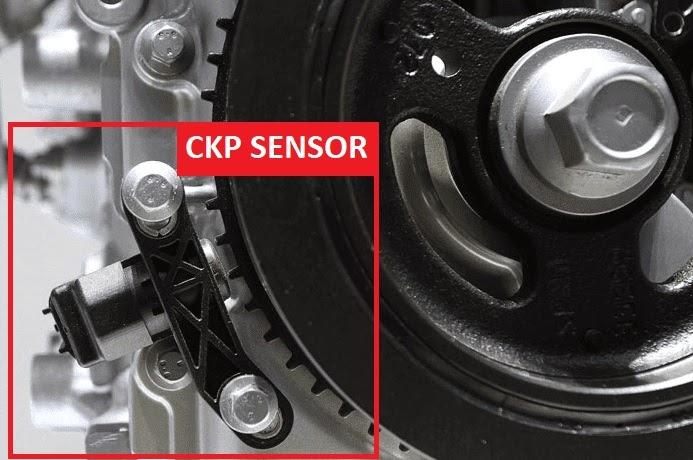
Where the Sensor Is Located
Accurate testing starts with access. The mounting position varies by platform but is typically near the lower timing cover, the bell housing, or alongside the harmonic balancer where the reluctor wheel passes closest. The common thread is proximity to the rotating member it measures, since the tip must sit within a fraction of a millimetre of the trigger teeth.
Consult the factory service literature for the exact mounting point and connector pinout before disassembly. On many transverse engines the unit hides behind the serpentine belt or intake manifold, so plan for partial component removal and protect the wiring during access. On rear-wheel-drive layouts it often lives at the bell housing reading a tone ring on the flywheel, which can mean working from underneath the vehicle.
Before you reach for tools, photograph the routing of the harness and connector. A quick reference image speeds reassembly and prevents the pinched or misrouted wires that cause comeback faults. If the unit sits low on the block where road grime collects, clean the area first so debris does not fall into the mounting bore once the part is removed. Small habits like these keep the job clean and the new component protected.
Access difficulty varies enormously between platforms, and underestimating it derails many repairs. A unit clipped to an accessible spot near the front pulley might take ten minutes, while one buried behind the intake on a transverse V6 can consume the better part of an afternoon. Estimate the labor honestly before quoting the job, because an optimistic guess on a hard-to-reach unit erodes both your margin and the customer's trust. Where the design allows, a service kit with an extension or a flexible socket can turn an awkward bolt into a manageable one.

Tools and Preparation You Will Need
Gathering the right equipment before you start avoids stopping mid-diagnosis. A reliable workflow uses:
- A bidirectional scan tool capable of reading live RPM and timing parameters.
- A digital multimeter with AC voltage and resistance ranges.
- An oscilloscope or labscope for waveform capture, ideal for intermittent faults.
- Back-probe pins or piercing probes to test without disconnecting the harness.
- A torque wrench and the correct socket for the mounting bolt.
- Dielectric grease, contact cleaner, and a non-magnetic feeler gauge for air-gap checks.
Always begin with the battery in a healthy state. A weak battery slows cranking speed, which lowers the signal amplitude from an inductive pickup and can produce misleading readings. Confirming battery voltage and connection integrity first removes a common source of false diagnoses.
A Simple Diagnostic Decision Path
When time is tight, a logical sequence keeps you from chasing the wrong lead. Work through the steps below and stop as soon as a test isolates the fault:
- Read stored and pending codes, then note the freeze-frame conditions to understand when the fault occurs.
- Verify battery health and connection integrity to rule out slow cranking.
- Watch live RPM during cranking; a missing or jittery value points to the signal circuit.
- Inspect the connector and harness for corrosion, chafing, and loose pins before condemning the part.
- Bench-test resistance or reference voltage, repeating the check hot if the complaint is heat-related.
- Confirm with a waveform capture when the symptom is intermittent.
- Check mechanical timing and the trigger wheel if a correlation code is present.
Following this order means each step either solves the problem or rules out a possibility, which is the surest way to deliver a repair that lasts and a customer who does not return with the same complaint.
Cleaning, Reinstalling, and Verifying the Repair
Once you confirm the pickup is at fault, careful installation protects your work. Clean the mounting bore and remove any metal filings that may cling to a magnetic tip. Set the air gap to specification where the design is adjustable, and torque the mounting bolt to the listed value to avoid both leaks and vibration-induced cracks.
Seat the connector fully until it clicks, and apply a light film of dielectric grease to guard against moisture and corrosion. Route the harness along its original path, securing it with the factory clips so it stays clear of hot or moving parts. After reassembly, clear the codes, run the relearn procedure if the platform requires one, and road-test the vehicle to confirm the symptom is gone and no new codes return.
Do not skip the relearn step on platforms that demand it. Modern controllers store a correction table that compensates for tiny manufacturing variations in the trigger wheel, and a fresh part shifts those values. Without the relearn, the engine may misfire counters trip or set a fresh correlation code even though the hardware is sound. A few minutes following the documented procedure saves a frustrating comeback over a repair that was, in truth, already complete.
Maintaining a Long-Lived Engine Shaft
The pickup only performs as well as the rotating assembly it measures, so engine internal health matters. Maintaining correct piston ring gap during a rebuild prevents blow-by that contaminates oil and accelerates bearing wear on the main journals.
Healthy compression rings keep combustion pressure where it belongs, while the oil control ring meters lubrication to the cylinder walls. A failing piston ring seal raises crankcase pressure and oil consumption, both of which shorten shaft life. Inspect each ring groove for carbon buildup at scheduled overhauls.
Contaminated oil is a quiet enemy of the rotating assembly. As blow-by pushes combustion byproducts past worn rings, the lubricant thins and loses its protective film, accelerating wear on the main and rod journals the pickup depends on. Sticking to the recommended oil grade and service interval does more to extend shaft life than almost any other single habit, and it keeps the trigger wheel clean enough to deliver a strong signal.
Clean lubrication and balanced rotation are the two strongest predictors of long shaft service life. Most premature failures trace back to neglected oil intervals, not metal fatigue.
Use quality-matched components for any rebuild. Browse the verified crankshaft options when sourcing replacement rotating assemblies, and match parts to your platform through our product category brand listings and engine-specific product category system groupings. Choosing the right part for the application is half the battle, and our listings are organized to make that selection straightforward.
When a Full Shaft Replacement Becomes Necessary
When wear exceeds tolerance, the entire rotating member must be replaced rather than just the electronics. This is a far larger undertaking, since the labor of an extensive engine teardown typically dwarfs the part itself. The contrast underscores why precise diagnosis pays off: swapping only the timing pickup is a modest job, while a complete rebuild ties up a bay for days.
Verified procurement records from documented partner projects, available in our cooperative-case archive, show fleets reducing repair spend by avoiding unnecessary full rebuilds. The recurring lesson is that a careful electronic diagnosis takes a fraction of the time a full teardown demands, and getting it right the first time keeps both the budget and the schedule intact.
For any owner or shop manager, the decision tree is straightforward. Confirm the timing signal first with the structured tests above. Only when the rotating assembly itself shows measurable wear, such as out-of-round journals or scored bearing surfaces, does the conversation move to a full replacement. Reaching that conclusion through evidence rather than guesswork protects the customer from paying for work the engine did not need.
Conclusion
Checking the timing pickup is a structured process: confirm symptoms, locate the unit, then validate it with scan data, a multimeter, and ideally an oscilloscope. Each method narrows the fault and protects you from replacing healthy parts.
Pair accurate diagnostics with disciplined lubrication and quality components, and the rotating assembly will deliver hundreds of thousands of reliable miles. To learn more about our engineering background, visit our about us page, explore the full Mettlead catalog, or reach our specialists directly through contact us for application-specific guidance.
Frequently Asked Questions
Can you drive with a failing crank position sensor?
It is risky. The engine may stall without warning, creating a safety hazard in traffic. Once timing-related codes appear, test and address the component promptly rather than continuing to drive.
Will a bad sensor always trigger a check-engine light?
Not always. Intermittent or heat-induced faults can cause stalling before a code stores permanently. Live-data monitoring during a no-start event is often more revealing than a static scan.
Do I need to clear codes after replacing the unit?
Yes. Clear stored fault codes and, on many platforms, perform a relearn or sync procedure so the ECU recalibrates its timing reference to the new component.
How long does the position sensor typically last?
Most units last 100,000 miles or more. Heat exposure, oil contamination, and vibration are the leading factors that shorten service life on high-mileage engines.
Is the failure related to the timing belt?
Indirectly. A stretched belt or skipped tooth changes the relative timing the pickup reports, which can mimic an electronic fault. Always verify mechanical timing before condemning the electronics.
Can I test the sensor without removing it from the engine?
In most cases, yes. Back-probing the connector lets you capture live voltage or a waveform during cranking without disturbing the mount. This approach is often preferable because it tests the unit under real operating conditions, including the heat and vibration that trigger intermittent faults.
What is the difference between an inductive and a Hall-effect pickup when testing?
An inductive type is a passive coil you test with resistance and AC voltage, producing a sine wave that strengthens with speed. A Hall-effect type is a powered device you test by verifying its reference supply and ground, producing a steady square wave regardless of engine speed. Identifying the type first tells you which measurements are meaningful.